Compressed air leaves the compressor carrying everything the machine ingested and everything it generated: atmospheric dust, pipe scale, condensed water, lubricant aerosol and hydrocarbon vapour. Left in the stream, these contaminants seize valves, foul instruments, spoil coating finishes and invalidate food and pharmaceutical batches. Filtration is not a single product decision. A plant has to choose among several distinct filter functions, assign each an efficiency grade, and place them in a sequence where every stage protects the one behind it. Get the type right but the order wrong, and an expensive high-efficiency element will load up in weeks instead of lasting a year.
A complete compressed air filter train uses four functional types: particulate filters for solid contamination, coalescing filters for water and oil aerosols, activated carbon filters for oil vapour and odour, and dust removal after-filters for desiccant carryover. Grades run from coarse pre-filtration at 3 to 5 microns down to high-efficiency coalescing at 0.01 micron, and the established installation order is bulk condensate removal first, then particulate pre-filtration, then the dryer, then coalescing filtration, then activated carbon last.
The sections below work through each decision in the order a system designer actually faces it.
What contaminants do compressed air filters actually remove?
Compressed air carries three categories of contamination, and each requires a different removal mechanism: solid particles are trapped mechanically, water and oil aerosols are coalesced into drainable liquid, and oil vapour can only be adsorbed onto activated carbon.
No single element handles all three. A filter sold as general purpose is usually a particulate element with a modest coalescing layer, and it will pass vapour-phase oil straight through regardless of how fine its rating claims to be.
| Contaminant | Typical source | Failure it causes | Removal mechanism |
| Solid particulate | Atmospheric dust, pipe corrosion, wear debris | Eroded valve seats, blocked orifices | Mechanical interception |
| Water aerosol | Humidity condensing as air cools | Corroded piping, diluted lubricant | Coalescing and drainage |
| Oil aerosol | Lubricant carryover | Stained product, fouled sensors | Coalescing, then drainage |
| Oil vapour | Volatilised lubricant in gas phase | Odour transfer, coating defects | Adsorption on carbon |
One limit deserves stating plainly because it is the most common misunderstanding in filtration specification: a filter removes liquid water and water aerosol, but it does not remove water vapour and cannot lower the pressure dew point. The Compressed Air and Gas Institute makes this distinction explicitly in its technical guidance, noting that filters handle bulk liquid and some aerosol only, while dew point reduction is the dryer’s function. A plant that installs progressively finer filters hoping to fix a wet-air problem will spend money and still find water at the point of use.
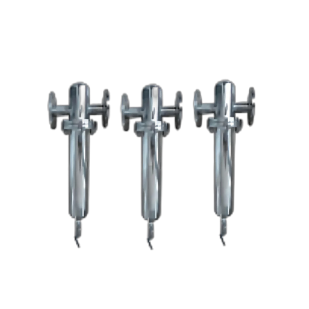
Because liquid loading is heavy in most installations, bulk condensate deserves dedicated treatment rather than being left to the elements. A cyclonic separator or inline water filter ahead of the filtration stages removes it at almost no pressure cost and stops the fine elements from being flooded, as covered in the guide to an Air Compressor Inline Water Filter.
The main compressed air filter types
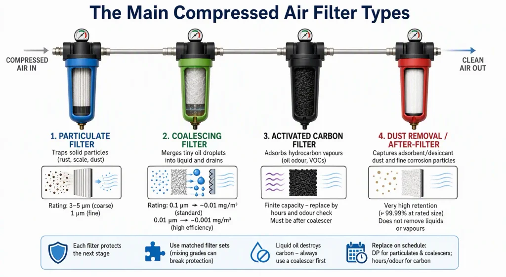
There are four types in general industrial use: particulate filters that trap solids, coalescing filters that merge fine droplets into drainable liquid, activated carbon filters that adsorb vapour-phase hydrocarbons, and dust removal after-filters that capture media carryover.
Each type occupies a defined position in the train and depends on the stage before it. Available Air Filters are generally specified as a matched set for this reason, since mixing grades from unrelated product families often produces a train whose stages no longer protect one another.
Particulate filters
A particulate element is a depth filter. Air passes through a pleated or wrapped medium and solids are captured by interception and impaction. Ratings are given as a micron value, typically 3 to 5 microns for a coarse pre-filter and 1 micron for a fine grade. The role is protective rather than final: it stops rust, scale and desiccant dust from reaching the coalescing stages, where solid loading would blind the media and drive differential pressure up long before the element is due for replacement. Particulate filters remove neither liquids in quantity nor vapour.
Coalescing filters
A coalescing element works in three steps. Fine droplets are captured in a glass-fibre medium, merge into larger droplets as they travel through the depth of the media, and are shed at a drainage layer into the bowl, with a re-entrainment barrier preventing the collected liquid from being picked back up by the airstream. Standard elements are rated around 0.1 micron and hold residual oil near 0.01 mg/m³; high-efficiency versions rated at 0.01 micron reach approximately 0.001 mg/m³. Efficiency improves on dry air, which is the technical reason the main coalescer normally sits after the dryer.
Activated carbon filters
Activated carbon removes what coalescing cannot touch: hydrocarbon molecules in the vapour phase. The mechanism is adsorption onto a vast internal pore surface rather than mechanical capture, and the capacity is finite. Once saturated, the bed stops working without any visible sign, so replacement is scheduled by hours and by downstream odour checks rather than by differential pressure. Carbon is also the most easily destroyed element in the train, because liquid oil blinds the pores within days. It must always be preceded by a working coalescing stage, never installed as a standalone filter on oily air.
Dust removal and after-filters
Dust removal elements are fine particulate filters used for a narrow purpose: capturing adsorbent or desiccant dust shed by a desiccant dryer, and catching corrosion particles in the last few metres of pipework. They achieve very high retention, in the region of 99.99 percent at their rated size, but they neither remove liquids nor adsorb vapour. Where a carbon adsorber is used, a dust filter after it is good practice because carbon fines can migrate downstream.
| Filter type | Removes | Typical rating | Position in train |
| Bulk water separator | Condensate, oil and water slugs | Not rated in microns | First, at aftercooler outlet |
| Particulate pre-filter | Rust, scale, dust, debris | 3 to 5 micron | Before the dryer |
| Coalescing filter | Water and oil aerosols, fine solids | 0.1 micron, 0.01 mg/m³ | After the dryer |
| High-efficiency coalescing | Ultrafine aerosols | 0.01 micron, 0.001 mg/m³ | After the coalescer |
| Activated carbon | Oil vapour, odour, taste | Not rated in microns | Last, after coalescing |
| Dust removal after-filter | Desiccant and carbon fines | 1 micron or finer | After desiccant or carbon |
Filter grades and micron ratings explained
Filter grades form a ladder rather than a menu: each grade is defined by the particle size it retains and the residual oil content it achieves, and grades are used in sequence so that coarse stages absorb the bulk load and protect the finer, more expensive stages behind them.
A micron rating describes the size at which an element retains particles. It says nothing on its own about oil aerosol performance, so a complete specification always pairs a particle rating with a residual oil figure. The progression runs from coarse particulate at 3 to 5 microns with no meaningful oil removal, through 1 micron fine particulate, to standard coalescing at 0.1 micron and 0.01 mg/m³ residual oil, then high-efficiency coalescing at 0.01 micron and 0.001 mg/m³, and finally activated carbon for vapour.
Two rules follow. Finer is not automatically better, because an element specified one grade too fine loads faster, raises differential pressure and costs energy without improving delivered air quality beyond what the process needs. And skipping a grade never saves money, because the stage that remains absorbs the load the missing stage was designed to take.
How grades map to ISO 8573-1 classes
ISO 8573-1 specifies purity as three independent parameters, particles, water and oil, each expressed as a class number. A full specification reads as three digits, for example Class 1.4.1 for particle class 1, water class 4 and oil class 1. The standard is defined and published as ISO 8573-1:2010.
| Class | Max particle size and concentration | Max oil content | Pressure dew point |
| 0 | As agreed between user and supplier | As agreed | As agreed |
| 1 | 0.1 micron, 0.1 mg/m³ | 0.01 mg/m³ | minus 70 degrees C |
| 2 | 1 micron, 1 mg/m³ | 0.1 mg/m³ | minus 40 degrees C |
| 3 | 5 micron, 5 mg/m³ | 1.0 mg/m³ | minus 20 degrees C |
| 4 | 15 micron, 8 mg/m³ | 5.0 mg/m³ | plus 3 degrees C |
Class 0 is not a purity level in itself but a placeholder for levels agreed contractually, which is why pharmaceutical, breathing air and semiconductor specifications should always be written as an explicit three-part class plus any additional validated requirements.

Matching filter grade to your application
Grade selection follows the end use, not the compressor model, because one compressor may feed a general workshop header and a food contact line that require completely different air quality.
The table gives starting combinations in installation order, all assuming a bulk water separator and pre-filter at the front and a correctly sized dryer.
| Application | Filter train | Typical target class |
| Workshop, pneumatic tools | Coalescing only | Oil 3, particles 3 |
| Plant header with instruments | Coalescing, high-efficiency coalescing | Oil 2, particles 2 |
| Spray painting and coating | Coalescing, high-efficiency, carbon | Oil 1, odour free |
| Food and beverage packaging | High-efficiency coalescing, carbon | Oil 1, particles 2 |
| Pharmaceutical and cleanroom | Fine particulate, high-efficiency, carbon | Oil 1 or Class 0 |
| Electronics and SMT | Coalescing, high-efficiency coalescing | Oil 1, particles 1 |
| Membrane or PSA feed | Coalescing, high-efficiency coalescing | Oil 1 |
Two checks apply to every row. The oil figure usually drives cost, so specify only the class the process genuinely needs; a workshop running Class 1 filtration across the whole header pays for energy and elements it cannot use. And where one compressor serves mixed end uses, filter at the branch rather than at the compressor, so the high-purity branch carries the high-purity cost.
The correct installation order for compressed air filters
The correct order is bulk condensate removal, particulate pre-filtration, drying, coalescing, then activated carbon, with a final point-of-use filter where the last few metres of pipe risk recontaminating the air.
Stage-by-stage sequence
- Aftercooler and bulk water separator. Cool the discharge to near ambient and drop out bulk condensate before it reaches any element. This stage carries the largest liquid load and should never be bypassed.
- Particulate pre-filter, 3 to 5 micron. Removes solids so the dryer and coalescer do not become filters for rust.
- Dryer. Reduces the pressure dew point so no further condensation forms downstream. Refrigerated dryers reach roughly plus 3 degrees C, desiccant dryers minus 40 degrees C or lower. Selection guidance for this stage is covered in the Air Compressor Dryer range.
- Coalescing filter after the dryer. Working on dry air, where efficiency is highest and the water load has already been removed.
- Activated carbon last. Protected from liquid oil by the coalescer immediately upstream, and followed by a dust filter where fines are a concern.
One legitimate variation exists at stage 4. Where oil carryover is high or the dryer is a desiccant type sensitive to liquid contamination, a protective coalescing element is also fitted ahead of the dryer. In that arrangement the upstream coalescer takes the bulk aerosol load and the downstream high-efficiency element polishes the air. What must not happen is relying on a single coalescer placed before the dryer to deliver final oil performance.
Installation mistakes that destroy filter performance
- Coalescer placed before the dryer instead of after it, so it handles maximum water loading and element life collapses.
- Carbon adsorber installed without a working coalescer upstream, saturating the bed within days.
- No pre-filter ahead of the dryer, allowing fouling and irreversible desiccant bed contamination.
- A single element expected to handle particles, aerosols and vapour at once.
- Filters sized to average flow rather than peak demand, so the element runs above rated velocity whenever the plant is busiest.
- Elements changed by calendar date only, with no regard to differential pressure or air quality results.
Point-of-use filtration
Header filtration does not guarantee quality at the tool. The last few metres of piping are frequently the dirtiest part of a system, especially where older galvanised or black iron lines remain in service, and flexible hoses shed particles of their own. A final coalescing or dust element at the critical drop protects the equipment that matters, and stabilising pressure there with adequate storage, through properly sized Air Receivers, prevents the filter from being blamed for pressure problems that are really volume problems.
Sizing, pressure drop and element life
Every filter must be sized for peak corrected flow at actual operating pressure and temperature, because an undersized element produces the same symptoms as a dirty one: high differential pressure, lost downstream pressure and wasted compressor energy.
Filter capacity is quoted at a reference pressure and inlet temperature, usually around 7 bar and 25 degrees C, and real installations rarely match those conditions. Higher temperature and lower pressure both raise the actual volumetric flow through the element, so a filter nominally rated for the compressor’s output can be significantly overloaded in service. Size on peak demand with headroom for expansion and apply the correction factors rather than accepting the catalogue figure.
Reading differential pressure
Differential pressure is the most useful indicator of filter condition. A clean element typically sits at 0.1 to 0.2 bar. As media loads, the figure climbs and the compressor must generate more pressure to push the same air through, which is energy consumed for no production benefit. A commonly used rule of thumb is that each additional 1 bar of pressure drop adds roughly 7 percent to compressor energy consumption. Replacement is normally triggered somewhere between 0.35 and 0.5 bar, with the exact figure set by the element supplier. A gauge in the red zone also means the element is close to bypass, at which point contamination travels around the media rather than through it.
Replacement intervals and warning signs
The usual baseline is 12 months or 8,000 operating hours, whichever arrives first. High dust, high ambient temperature and multi-shift operation all shorten that interval, and quarterly inspection of the pre-filter is sensible in foundries, textile plants and similar sites.
Three signs indicate a filter has already failed rather than being about to fail. Visible oil on downstream pipework, cylinders or spray equipment means the coalescing element is saturated and releasing what it captured. Hydrocarbon odour or taste in process air means the carbon bed is exhausted and passing vapour through. Differential pressure that keeps rising after an element change usually indicates the element is undersized or the wrong grade for the duty.
FAQ
Three questions come up repeatedly once a train has been specified and is running: whether a filter can substitute for a separator, whether orientation matters, and what evidence auditors will ask for.
Can a compressed air filter replace a water separator?
No. They solve different problems. A separator removes bulk liquid condensate by cyclonic action and protects the filtration stages, while a filter removes aerosols and fine solids. Most well-designed systems use both, with the separator first.
Does filter orientation affect performance?
Yes. Coalescing elements depend on gravity to drain captured liquid from the bowl, and most are designed for vertical flow with the drain at the lowest point. A horizontal housing, or one without a functioning drain, allows collected liquid to be re-entrained and defeats the element regardless of its rating.
Is documentation available for audits in food and pharmaceutical plants?
Usually yes, and it should be requested at the specification stage rather than after installation. Auditors typically ask for tested performance against ISO 8573-1 classes, the material of construction in contact with the air, and a documented replacement schedule. Specifying these three items in the purchase enquiry avoids retrofitting evidence later.