
Guía completa de tallas
Un jefe de fábrica que encarga un compresor de aire de 100 kW porque “esa era la potencia nominal del antiguo” tiene una probabilidad de 50% de comprar la máquina equivocada. Es posible que el compresor antiguo estuviera sobredimensionado desde el principio, algo habitual cuando el responsable de las especificaciones originales añadió un margen de 20% para la expansión, el instalador añadió 10% por seguridad y el responsable de mantenimiento añadió otros 10% porque pensaba que uno más grande era más seguro. El resultado es un compresor que funciona a una carga de 60%, consumiendo electricidad para generar aire comprimido que la fábrica no utiliza, lo que supone un derroche de entre $15 000 y $40 000 al año en consumo energético innecesario. En el extremo opuesto, una fábrica que añade líneas de producción sin reevaluar su suministro de aire comprimido descubre el error de dimensionamiento cuando las herramientas neumáticas pierden par, las máquinas de envasado fallan en la alimentación y la alarma de presión suena cada vez que dos grandes consumidores funcionan simultáneamente. Un compresor de capacidad insuficiente cuesta tanto como uno sobredimensionado —no en electricidad, sino en tiempo de inactividad de la producción, defectos de calidad y el coste de capital de una sustitución de emergencia—.
Un compresor de aire industrial debe dimensionarse para suministrar el volumen total de aire comprimido que requieran todos los consumidores simultáneos a la presión más alta que exija cualquiera de ellos, más un margen de entre 15% y 25% para tener en cuenta las fugas, la futura expansión y las cargas máximas intermitentes. Para una planta de fabricación típica de tamaño pequeño a mediano, esto supone un compresor de tornillo rotativo de entre 30 y 75 kW que suministre de 5 a 15 metros cúbicos por minuto a una presión de entre 7 y 10 bar para uso industrial general, ampliándose a unidades de entre 132 y 250 kW que suministren de 20 a 45 metros cúbicos por minuto para plantas más grandes con múltiples líneas de producción. El tamaño exacto se determina sumando el consumo en CFM o m³/min de cada herramienta neumática, cilindro, válvula y boquilla de purga que funcione simultáneamente, y convirtiendo luego ese total a la potencia de entrada del compresor necesaria para suministrarlo a la presión especificada. No existe una respuesta universal —una fábrica textil, una cadena de montaje de automóviles, una planta de envasado de alimentos y un taller mecánico tienen perfiles de aire comprimido fundamentalmente diferentes—, pero la metodología para llegar a la respuesta correcta es la misma para todas las fábricas.
Por qué es fundamental el dimensionamiento de los compresores de aire industriales
Un compresor dimensionado correctamente minimiza el coste total de propiedad al equilibrar tres objetivos: el coste de inversión, el coste energético a lo largo de su vida útil y el coste de producción derivado de las interrupciones que provocan paradas. Un compresor sobredimensionado supone un derroche de energía y de capital. Uno infradimensionado supone una pérdida de producción. La diferencia se traduce en decenas o cientos de miles de dólares a lo largo de los diez años de vida útil del compresor.
El coste del sobredimensionamiento
Un compresor sobredimensionado —con una potencia nominal de 30%+ por encima de la demanda máxima— funciona de forma ineficiente. Un compresor de tornillo rotativo de 75 kW con una potencia específica de 6,5 kW/m³/min a plena carga puede llegar a consumir entre 8,5 y 9,0 kW/m³/min con una carga de 50% bajo un control de carga/descarga, ya que el motor consume entre 25 y 35% de la potencia a plena carga durante los periodos sin carga.
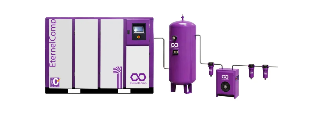
Imaginemos una fábrica con una demanda máxima real de 9 m³/min a 7 bar que instala un compresor de 90 kW con una capacidad nominal de 15 m³/min en lugar de una unidad de 55 kW con una capacidad nominal de 10 m³/min. La máquina sobredimensionada funciona a una carga media de 60% con una potencia específica efectiva de 8,0 kW/m³/min en lugar de 6,5. Con más de 6.000 horas al año a $0,10/kWh, consume $7.200 más al año en electricidad. Además, su coste de adquisición es entre $10.000 y $15.000 mayor. El coste a diez años del sobredimensionamiento: entre $82 000 y $87 000, lo que equivale aproximadamente al precio de un compresor nuevo.
El coste de elegir un tamaño demasiado pequeño
Un compresor de capacidad insuficiente genera costes debido a las interrupciones en la producción. Cuando la demanda supera a la oferta, la presión del sistema desciende. A 0,5 bar por debajo del punto de consigna, las herramientas pierden par y velocidad. A 1,0 bar por debajo del punto de consigna, los cilindros no completan sus carreras, las válvulas no se accionan y los equipos automatizados fallan. El coste varía según el sector: $2.000/hora para el envasado de alimentos, $5.000/hora en el montaje de automóviles, $10.000/hora en la fabricación de semiconductores— y una sola pérdida de producción de 8 horas puede superar el ahorro energético de la máquina más pequeña en más de diez años.
Entender los conceptos de CFM, PSI y kW: las tres cifras que definen el tamaño de un compresor
El tamaño de un compresor viene determinado por tres valores interrelacionados: el caudal (CFM o m³/min), la presión (PSI o bar) y la potencia de entrada (kW o HP). La relación entre ellos es la potencia específica del compresor —los kW necesarios por m³/min a una presión determinada— y este es el dato más importante de la ficha técnica de un compresor para un comprador industrial.
El caudal es acumulativo para los consumidores. Tres herramientas que consumen 3 m³/min cada una requieren al menos 9 m³/min del compresor. Al duplicar el caudal, se duplica aproximadamente la potencia del motor necesaria a la misma presión.
La mayoría de las aplicaciones industriales generales funcionan a una presión de entre 6 y 8 bar (90-115 PSI). Los procesos especializados, como el soplado de botellas de PET, requieren entre 30 y 40 bar. La presión necesaria en la fábrica viene determinada por el consumidor que requiere la presión más alta, no por la media. El caudal del compresor disminuye a medida que aumenta la presión de descarga: una unidad con un caudal nominal de 10 m³/min a 7 bar puede suministrar 9,2 m³/min a 8 bar y 8,5 m³/min a 10 bar. Los cálculos de dimensionamiento deben basarse en el caudal a la presión requerida, no en el punto de funcionamiento óptimo. Debe tenerse en cuenta la caída de presión en las tuberías, los filtros y los secadores: una fábrica que necesite 6 bar en la herramienta, con una pérdida total del sistema de 0,8 bar, requiere que el compresor suministre un mínimo de 6,8 bar, lo que normalmente se especifica en 7,5 bar.
| Tipo de compresor | Potencia específica típica a 7 bar | Ejemplo: una unidad de 75 kW suministra aproximadamente |
|---|---|---|
| Tornillo rotativo lubricado con aceite, velocidad fija | 6,0–7,0 kW/m³/min | 10,5–12,5 m³/min |
| Tornillo rotativo lubricado con aceite, VSD | 5,8–6,8 kW/m³/min | 11,0–13,0 m³/min |
| Compresor de tornillo sin aceite, de velocidad fija | 6,5–7,5 kW/m³/min | 10,0–11,5 m³/min |
| Pistón lubricado con aceite (alternativo) | 7,5–9,0 kW/m³/min | 8,3–10,0 m³/min |
| Centrífugo (rango de más de 300 kW) | 5,5–6,5 kW/m³/min | 11,5–13,6 m³/min |
Una fábrica que necesita 15 m³/min a 7 bar, con una potencia específica de 6,5 kW/m³/min, requiere aproximadamente 97,5 kW, lo que, redondeando, da una potencia nominal estándar de 90 kW o 110 kW.
Cómo calcular la demanda de aire comprimido de tu fábrica
El cálculo se realiza en cuatro pasos: hacer un inventario de todos los equipos neumáticos; determinar el consumo de aire de cada elemento a partir de la ficha técnica, una medición directa o una estimación del sector; aplicar un factor de ciclo de trabajo para el uso intermitente; y sumar la demanda máxima simultánea.
Paso 1: Realizar un inventario de todos los equipos neumáticos
Recorre la planta de producción y haz una lista: herramientas neumáticas manuales (llaves de impacto, amoladoras, lijadoras, taladradoras, pistolas pulverizadoras); maquinaria neumática fija (máquinas CNC, robots de manipulación, prensas, máquinas de llenado y taponado); cilindros y actuadores neumáticos; válvulas y controles; equipos de soplado y limpieza (pistolas de aire, boquillas, cuchillas de aire); aire de proceso (agitación, burbujeo, aireación, transporte); y fugas.
Paso 2: Determinar el consumo de aire individual
Fuentes por orden de fiabilidad: ficha técnica del fabricante, medición directa con un caudalímetro portátil o estimaciones del sector:
| Equipamiento | Consumo típico de aire | Ciclo de trabajo (típico) |
|---|---|---|
| Llave de impacto de 1/2 pulgada | 0,1–0,2 m³/min | 10–30% |
| Amoladora angular (4 pulgadas) | 0,3–0,5 m³/min | 20–50% |
| Taladro neumático (3/8 de pulgada) | 0,1–0,2 m³/min | 10–30% |
| Pistola pulverizadora de pintura (HVLP) | 0,3–0,5 m³/min | 30–60% |
| Cilindro neumático (diámetro interior de 50 mm, carrera de 200 mm) | 0,002 m³ por carrera | Depende de la aplicación |
| Boquilla de purga (3 mm) | 0,2–0,4 m³/min | 10–50% |
| Bomba de diafragma neumática (1 pulgada) | 0,5–1,5 m³/min | 20–80% |
| Transportador neumático (por metro) | 0,5–1,0 m³/min | 50–100% |
Paso 3: Aplicar el ciclo de trabajo
El ciclo de trabajo es la fracción de tiempo durante la cual el equipo consume realmente aire comprimido. Una amoladora que se utiliza durante 15 minutos de cada hora tiene un ciclo de trabajo de 25%. Una boquilla de soplado que funciona de forma continua tiene un ciclo de trabajo de 100%. Al multiplicar el consumo a plena carga del equipo por su ciclo de trabajo se obtiene el consumo medio, que resulta más realista a la hora de dimensionar el sistema que la suma de todos los valores a plena carga.
El ciclo de trabajo es el origen de la mayoría de los errores de dimensionamiento. Un calculista sin experiencia suma el consumo a plena carga de todas las herramientas de la fábrica y obtiene una demanda que es entre dos y tres veces superior al pico real. El resultado es un compresor excesivamente sobredimensionado que funciona de forma ineficiente y desperdicia energía durante toda su vida útil. Una fábrica con diez amoladoras, cada una con un caudal nominal de 0,4 m³/min, no necesita un compresor que suministre 4,0 m³/min solo para las amoladoras. Si las amoladoras se utilizan el 25% del tiempo y, de media, funcionan dos simultáneamente, la demanda de las amoladoras es de 0,2 m³/min de media y de 0,8 m³/min en pico —una quinta parte de la suma simplista—.
Paso 4: Suma de la demanda máxima simultánea
La demanda máxima simultánea es el caudal máximo que consume la fábrica en cualquier momento durante su funcionamiento normal. Se calcula determinando qué equipos pueden funcionar al mismo tiempo y sumando su consumo de aire según el ciclo de trabajo aplicable durante el periodo de máxima demanda.
En el caso de una pequeña fábrica que cuente con el siguiente equipamiento:
| Equipamiento | Cantidad | Consumo por unidad | Ciclo de trabajo | Uso simultáneo eficaz | Flujo máximo |
|---|---|---|---|---|---|
| Llaves de impacto | 4 | 0,15 m³/min | 20% | 2 a la vez | 0,30 m³/min |
| Amoladoras angulares | 3 | 0,40 m³/min | 30% | 2 a la vez | 0,80 m³/min |
| Boquillas de purga | 5 | 0,25 m³/min | 50% | 3 a la vez | 0,75 m³/min |
| Cilindros neumáticos | 8 | 0,05 m³/min | 40% | 5 cada vez | 0,25 m³/min |
| Máquina de envasado | 1 | 1,50 m³/min | 80% | Continuo | 1,50 m³/min |
| Demanda máxima total | — | — | — | — | 3,60 m³/min |
| Margen de fuga (15%) | — | 3,60 m³/min | 15% | — | 0,54 m³/min |
| Ampliación futura (10%) | — | 3,60 m³/min | 10% | — | 0,36 m³/min |
| Caudal total de dimensionamiento | — | — | — | — | 4,50 m³/min |
Un compresor dimensionado para esta fábrica con una presión de descarga de 7 bar sería, aproximadamente, una unidad de tornillo rotativo lubricada con aceite de 30 kW. Esta es la metodología en su forma más básica. Las fábricas más grandes, con patrones de producción más complejos, se benefician de un estudio de registro de datos durante una o dos semanas para captar el perfil real de la demanda, en lugar de basarse en ciclos de trabajo estimados.
Un compresor grande frente a varios compresores pequeños: la decisión sobre el diseño del sistema
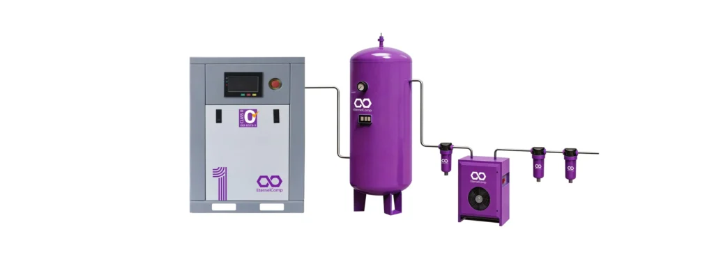
Un único compresor dimensionado para la demanda máxima es la configuración más sencilla y la que presenta un menor coste de inversión, pero carece de redundancia y funciona con baja eficiencia durante los periodos de menor demanda. Varios compresores más pequeños con un secuenciador maestro suponen un coste adicional de entre 15% y 30% en la compra e instalación, pero proporcionan una redundancia N+1 —lo que significa que el fallo de un compresor no detiene la producción — y el secuenciador activa y desactiva los compresores según fluctúa la demanda, manteniendo cada unidad en funcionamiento en su punto de carga más eficiente. En el caso de las fábricas con un solo turno o con una demanda muy variable, el uso de varios compresores suele suponer la configuración con menor coste total de propiedad a pesar del mayor coste de inversión, ya que el ahorro energético en carga parcial que se consigue al hacer funcionar un compresor pequeño a plena carga en lugar de uno grande a una carga del 40% compensa con creces el sobrecoste en un plazo de tres a cinco años.
Configuración con un solo compresor
Un único compresor dimensionado para la demanda máxima de la fábrica es la opción adecuada cuando:
- La demanda máxima y la media son similares —con una diferencia de 20% entre ambas—, lo que significa que el compresor funciona con un alto factor de carga durante la mayor parte de sus horas de funcionamiento.
- La fábrica funciona en uno o dos turnos, con un ritmo de producción relativamente constante.
- El presupuesto de inversión es limitado y la redundancia no es fundamental
- La fábrica puede permitirse entre 1 y 3 días de interrupción de la producción para llevar a cabo una reparación importante del compresor.
| Ventajas del compresor único | Desventajas del compresor único |
|---|---|
| El menor coste de compra e instalación | Sin redundancia: un solo fallo detiene la producción |
| El programa de mantenimiento más sencillo | Baja eficiencia a carga parcial si la demanda varía |
| Ocupación de espacio mínima | Requiere un depósito de aire de mayor capacidad para cargas transitorias |
| Punto único de control y supervisión | La parada por mantenimiento requiere la interrupción total de la producción |
Configuración con varios compresores
El uso de dos o más compresores que funcionan en secuencia, normalmente bajo el control de un controlador maestro central, es la opción adecuada cuando:
- La demanda varía considerablemente —en más de 30%— entre turnos o entre días de producción.
- La fábrica funciona las 24 horas del día y no puede permitirse paradas en la producción.
- La demanda máxima supera los 200 kW, por lo que resulta complicado, desde el punto de vista logístico, transportar, instalar y mantener un solo compresor.
- La fábrica tiene previsto ampliar su capacidad de producción por fases y quiere que la incorporación de nuevos compresores se adapte al crecimiento de la demanda.
Una configuración habitual y eficiente consiste en un compresor de carga base dimensionado para una demanda máxima de entre 60% y 70%, más un compresor de ajuste —a ser posible con variador de velocidad— que se encarga de los 30% a 40% restantes y se adapta a las fluctuaciones de la demanda. Esta configuración ofrece casi toda la flexibilidad de un sistema con varios compresores por aproximadamente el 70% del coste de inversión de un sistema N+1 completo con varias unidades del mismo tamaño.
Para las fábricas que estén evaluando comprar un compresor, la decisión sobre el diseño del sistema debe tomarse antes de solicitar presupuestos, ya que la diferencia de precio entre un presupuesto para una sola unidad y uno para varias unidades es lo suficientemente grande como para afectar al presupuesto de compra.
Adecuación del tipo de compresor a la aplicación de fábrica
La elección del tipo de compresor —de pistón alternativo, de tornillo rotativo lubricado con aceite, de tornillo rotativo sin aceite, centrífugo o de espiral— viene determinada por cuatro factores: los requisitos de calidad del aire de la fábrica, las horas de funcionamiento diarias, el rango de caudal y el presupuesto tanto para la adquisición como para el mantenimiento. Los compresores de pistón son la opción más económica para aplicaciones de bajo ciclo de trabajo por debajo de los 20 kW. Los compresores de tornillo rotativo lubricados con aceite predominan en el rango de 15 a 300 kW para la fabricación en general. Los compresores de tornillo rotativo sin aceite cubren el mismo rango de potencia en aplicaciones que requieren aire libre de contaminantes. Los compresores centrífugos son la opción más eficiente por encima de los 300 kW para aplicaciones de servicio continuo. El perfil operativo de la fábrica, y no el folleto comercial del compresor, es lo que debe determinar qué tipo se elige.
Correspondencia entre aplicación y tipo
| Tipo de fábrica | Requisitos típicos de caudal | Tipo de compresor recomendado | Aspectos clave a tener en cuenta |
|---|---|---|---|
| Taller pequeño, uso esporádico | 0,5–3 m³/min | Pistón (alternativo) | Bajo coste de adquisición, alto nivel de ruido, ciclo de trabajo limitado |
| Taller de reparación de coches | 2–5 m³/min | Pistón o tornillo rotativo pequeño | Ciclo de trabajo moderado, uso mixto de herramientas |
| Taller mecánico general | 3–8 m³/min | Tornillo rotativo lubricado con aceite | De forma continua durante los turnos, calidad del aire moderada |
| Fabricación de metales | 5–15 m³/min | Tornillo rotativo lubricado con aceite | Alta demanda intermitente por parte de amoladoras y herramientas |
| Envasado y procesamiento de alimentos | 5–20 m³/min | Tornillo rotativo sin aceite | El aire entra en contacto con el producto; no se admite ninguna contaminación. |
| Fabricación farmacéutica | 8–30 m³/min | Tornillo rotativo sin aceite | Normas reglamentarias sobre la calidad del aire |
| Montaje de vehículos | 15-50 m³/min | Compresor de tornillo rotativo lubricado con aceite o sin aceite | Alta demanda continua, algo de aire crítico |
| Fábrica textil | 20-60 m³/min | Tornillo rotativo lubricado con aceite | Alta demanda continua, calidad del aire moderada |
| Gran empresa química o refinería | 50–200+ m³/min | Centrífuga | Demanda continua muy elevada, presupuesto de inversión elevado |
El compresor de tornillo rotativo es la opción predeterminada para la mayoría de las fábricas en el rango de 5 a 200 m³/min, ya que ofrece el mejor equilibrio entre coste de adquisición, eficiencia energética, facilidad de mantenimiento y fiabilidad en una amplia gama de condiciones de funcionamiento. Para aquellas fábricas que necesiten un conocimiento más profundo de tipos de compresores industriales Antes de tomar una decisión, un análisis de todas las tecnologías disponibles, con sus ventajas y limitaciones, garantiza que las necesidades de la fábrica se ajusten correctamente a las prestaciones del compresor.
Consideraciones sobre el dimensionamiento específicas de cada sector
Los distintos sectores tienen patrones de demanda de aire comprimido diferentes, y el método de dimensionamiento debe tener en cuenta estas diferencias:
Alimentación y bebidas. El aire que entra en contacto con el producto debe estar libre de aceite y filtrado para eliminar partículas y microorganismos. El sistema de aire suele dividirse en dos niveles de presión: alta presión para los controles y accionamientos neumáticos, y baja presión para las aplicaciones en contacto con el producto. Los secadores y los sistemas de filtración representan una parte mayor del coste total del sistema que en la fabricación en general.
Fabricación de metales. La demanda es intermitente y alcanza picos, impulsada por el uso simultáneo de múltiples herramientas neumáticas y el funcionamiento cíclico de las máquinas CNC. El perfil de carga es muy variable, lo que hace que un compresor con variador de velocidad (VSD) o un sistema con varios compresores sea la opción más eficiente. Los requisitos de calidad del aire son moderados.
Sector textil. La demanda es continua y de gran volumen, impulsada por los telares de chorro de aire, las máquinas de hilado y el transporte neumático. El aire debe estar seco para evitar que la humedad dañe la fibra y el tejido, lo que hace que un secador de aire comprimido Esencial. El perfil de carga es constante, lo que favorece el uso de compresores grandes de velocidad fija con alta eficiencia a plena carga.
Electrónica y semiconductores. Los requisitos de calidad del aire son los más estrictos de todos los sectores. La compresión sin aceite, el secado por desecante hasta un punto de rocío de -40 grados Celsius y la filtración para eliminar partículas inferiores a 0,01 micras son características estándar. El coste del compresor representa una pequeña fracción del coste total del sistema de aire comprimido, y es habitual sobredimensionarlo para garantizar la fiabilidad.
El papel de los depósitos de aire comprimido en el dimensionamiento de los sistemas
El depósito de aire almacena aire comprimido entre el compresor y el sistema de distribución, lo que reduce las necesidades de caudal máximo al amortiguar los picos de demanda a corto plazo y reducir los ciclos de funcionamiento del compresor. Un depósito de tamaño adecuado puede reducir la capacidad necesaria del compresor entre un 10 y un 20%.
| Tipo de control del compresor | Volumen recomendado del receptor | Objetivo |
|---|---|---|
| Carga/descarga (velocidad fija) | 10-15 L por L/s | Evita los ciclos cortos y amortigua los picos de demanda |
| Variador de velocidad (VSD) | 5–8 L por L/s | Solo amortigua los transitorios de presión |
| Varios compresores con secuenciador | 5–10 L por L/s | Almacenamiento en búfer a nivel del sistema |
| Compresor de pistón | 15–25 L por L/s | Suaviza las fluctuaciones en la salida y evita los ciclos cortos |
El depósito reduce los ciclos del compresor al proporcionar un volumen de aire almacenado del que el sistema puede abastecerse entre los puntos de consigna de presión superior e inferior. Un compresor de carga/descarga con un depósito pequeño alterna entre los estados de carga y descarga cada pocos segundos, lo que provoca el sobrecalentamiento del motor y el desgaste prematuro del bloque compresor. Un depósito más grande alarga la duración de los ciclos, reduce el número de arranques por hora y prolonga la vida útil del compresor.
Para las fábricas que estén evaluando Dimensionamiento de los depósitos de aire comprimido, el depósito debe tener un tamaño suficiente para que el compresor funcione durante al menos entre 30 y 60 segundos entre ciclos, lo que da tiempo al motor para enfriarse entre arranques. Este requisito suele determinar el tamaño del depósito en mayor medida que la necesidad de amortiguar la demanda.
Ubicación del receptor y caída de presión
El receptor debe situarse lo más cerca posible de la descarga del compresor, antes del secador y los filtros. Esta ubicación tiene dos funciones: permite que el receptor actúe como amortiguador de pulsaciones, suavizando el caudal de descarga del compresor antes de que entre en el secador, y proporciona un volumen de aire húmedo y caliente en el que la humedad puede condensarse y drenarse antes de que el aire llegue al secador, reduciendo así la carga de humedad de este último.
Un receptor secundario situado cerca de un gran consumidor intermitente —como una prensa neumática que consume 5 m³/min durante 3 segundos cada 30 segundos— puede evitar la caída de presión que, de otro modo, este consumidor provocaría en el sistema de distribución principal. El tamaño del receptor secundario se determina en función del volumen de demanda del consumidor y de la caída de presión aceptable, y aísla la carga intermitente del resto del sistema.
Errores habituales en el dimensionamiento que suponen un gasto para las fábricas
El error más costoso en el dimensionamiento de un compresor es comprarlo basándose en los datos de la placa de características del motor del compresor antiguo sin medir la demanda real de la fábrica. El segundo error más costoso es añadir un margen excesivo en cada fase del proceso de dimensionamiento: el ingeniero añade 20%, el jefe de proyecto añade 10% y el responsable de compras redondea al tamaño estándar superior—, lo que da como resultado un compresor con un sobredimensionamiento de entre 30% y 50%. El tercer error más costoso es ignorar las fugas, que suelen representar entre 15% y 30% de la demanda de aire comprimido de una fábrica y que no se pueden solucionar por mucho que se sobredimensione el compresor; la respuesta correcta a las fugas es un programa de reparación de fugas, no un compresor más grande.
El problema de la acumulación de márgenes
| Persona | Margen añadido | Sobredimensionamiento acumulativo |
|---|---|---|
| Ingeniero de planta que calcula la demanda | +15% | 15% |
| Revisión por parte del responsable de ingeniería | +15% | 32% |
| Redondeo de las compras al tamaño estándar | +10% | 46% |
| El instalador elige la talla superior “por si acaso” | +10% | 60% |
Un compresor dimensionado para 60% por encima de la demanda funciona a una carga media de ~63% con una potencia específica reducida. El desperdicio a lo largo de diez años para una unidad de la clase de 75 kW: $50 000–$80 000. La solución: designar a una persona responsable, basar el dimensionamiento en datos medidos con un único margen de 15–20% y rechazar cualquier margen adicional sin una justificación documentada.
El punto ciego de las fugas
Una fábrica que no cuenta con un sistema de gestión de fugas suele perder entre 20 y 30% de producción de aire comprimido debido a las fugas —que se producen las 24 horas del día, los 7 días de la semana— y que consumen electricidad para comprimir aire que nunca llega al punto de uso. Un compresor de 75 kW que funciona 6.000 horas a $0,10/kWh cuesta aproximadamente $45.000 al año. Con una fuga de 25%, eso supone $11.250 al año. Un detector ultrasónico cuesta entre $500 y $2.000, y una inspección de toda la planta cuesta entre $2.000 y $5.000; ambas inversiones se amortizan en un plazo de 2 a 6 meses. Dimensiona el compresor en función de la demanda prevista y deja que el programa de reparaciones reduzca la demanda real hasta el valor de dimensionamiento.
Cuándo recurrir a un profesional para realizar una auditoría del aire comprimido
Una auditoría del aire comprimido realizada por un profesional certificado proporciona los datos medidos que convierten el dimensionamiento del compresor de una estimación en un cálculo de ingeniería. La auditoría mide el caudal, la presión, el consumo eléctrico y el punto de rocío en múltiples puntos del sistema durante un periodo de entre 7 y 14 días, lo que genera un conjunto de datos que revela el perfil de demanda real de la fábrica, las caídas de presión en el sistema de distribución, la tasa de fugas y la eficiencia de los equipos existentes. La auditoría cuesta entre $5.000 y $15.000 e identifica un ahorro energético de entre el 20% y el 40% del coste energético anual del aire comprimido. Para una fábrica que gasta $45 000 al año en electricidad para el aire comprimido, la auditoría se amortiza en un plazo de entre 3 y 8 meses solo con los ahorros identificados. Los datos de dimensionamiento que proporciona la auditoría son una ventaja añadida que hace que la inversión merezca la pena incluso si no se sustituye ningún equipo.
Cuándo está justificada una auditoría
Una auditoría del sistema de aire comprimido resulta rentable en las siguientes situaciones:
- La fábrica está sustituyendo su compresor principal y el nuevo compresor costará más de $30 000. A este precio, el coste de un error de dimensionamiento supera el coste de la auditoría.
- La demanda de aire comprimido de la fábrica ha cambiado —se han incorporado nuevos equipos, se han retirado otros antiguos y se han modificado los turnos— y nadie sabe cuál es realmente la demanda actual.
- La factura de electricidad de la fábrica correspondiente al aire comprimido parece elevada, pero nadie ha cuantificado cuál sería un importe “razonable”.
- La fábrica está barajando la posibilidad de instalar un compresor con variador de velocidad (VSD) y necesita los datos del perfil de carga para determinar si la inversión adicional que supone el VSD resultará rentable.
- La producción de la fábrica se ha visto interrumpida por episodios de baja presión y la causa no está clara: ¿se debe a que el compresor es de capacidad insuficiente, o bien a una restricción en las tuberías o a una obstrucción en el filtro que provoca una caída de presión localizada?
Para aire comprimido para la fabricación En aquellas aplicaciones en las que la producción depende de un suministro de aire fiable, la auditoría es una garantía frente al coste que supone un dimensionamiento incorrecto. El coste de un compresor mal dimensionado —en forma de energía desperdiciada, tiempo de inactividad en la producción o ambos— se mide en decenas de miles de dólares al año. El coste de la auditoría es una fracción de lo que supone ese desperdicio en un solo año.
Resultados de la auditoría
Un informe profesional de auditoría del aire comprimido incluye:
- Un gráfico del perfil de demanda que muestra el caudal en función del tiempo durante el periodo de medición, con anotaciones sobre los cambios de turno, los descansos y los eventos de alta demanda conocidos
- Un perfil de presión que muestra la presión en la descarga del compresor y en cada punto de uso medido, en el que se indican la ubicación y la magnitud de las caídas de presión.
- Una medición de la carga de fugas realizada durante un periodo sin producción, en el que todos los consumidores intencionales están desconectados, que cuantifica la tasa de fugas e identifica las fugas más importantes.
- Un análisis de la potencia y el consumo energético que muestra la energía total consumida y la potencia específica en cada punto de carga
- Una medición de la calidad del aire que muestra el punto de rocío, el nivel de partículas y el contenido de aceite en puntos críticos
- Una lista de recomendaciones ordenadas por prioridad, con los costes y ahorros estimados para cada medida, organizada de la que se amortiza más rápido a la que tarda más en amortizarse
El perfil de demanda resultante de la auditoría es la respuesta definitiva a la pregunta: “¿Qué tamaño de compresor necesita mi fábrica?”. Sustituye las estimaciones por datos y ofrece la seguridad necesaria para invertir entre $30 000 y $150 000 en un compresor, sabiendo que es del tamaño adecuado.
Conclusión
El tamaño adecuado para un compresor de aire de fábrica es aquel que cubre la demanda máxima simultánea de todos los consumidores de aire comprimido, más un margen único de entre 15% y 20% para tener en cuenta las fugas y la expansión, a la presión más alta que requiera cualquier consumidor más la caída de presión a lo largo del sistema de distribución. Para llegar a esta cifra es necesario seguir un proceso sistemático: hacer un inventario de todos los equipos neumáticos de la fábrica, determinar su consumo de aire a la presión de funcionamiento, aplicar un ciclo de trabajo realista, sumar el pico simultáneo, añadir el margen único y convertir el caudal y los requisitos de presión en un modelo de compresor y una potencia de motor.
El proceso no es difícil, pero exige disciplina. La disciplina de medir en lugar de estimar. La disciplina de resistir la tentación de añadir “solo un poco más” de margen en cada paso. La disciplina de reparar las fugas antes de comprar un compresor más grande. La disciplina de invertir en una auditoría cuando lo que está en juego lo justifica. Una fábrica que siga este proceso comprará un compresor que se adapte a su demanda, funcione de manera eficiente durante toda su vida útil y cueste lo mínimo posible en cuanto a adquisición, instalación, funcionamiento y mantenimiento. Una fábrica que se salte el proceso y se base en conjeturas probablemente se equivocará, y pagará por ese error en cada factura de electricidad durante los próximos diez años.
Preguntas frecuentes
¿Cuál es la diferencia entre CFM y SCFM a la hora de elegir el tamaño adecuado de un compresor de aire?
El CFM (pies cúbicos por minuto) es el caudal en las condiciones reales de admisión del compresor: la temperatura, la presión y la humedad del aire que entra en el compresor. El SCFM (pies cúbicos estándar por minuto) es el caudal corregido a condiciones estándar, normalmente a una presión absoluta de 1 bar, 20 grados Celsius y una humedad relativa de 0%. Al comparar compresores de diferentes fabricantes, utilice siempre el SCFM o el FAD (caudal de aire libre) según la norma ISO 1217 para garantizar una comparación equitativa. Un compresor con una potencia nominal de 100 CFM en condiciones de admisión a gran altitud puede proporcionar un caudal más bajo que uno con una potencia nominal de 95 SCFM en condiciones estándar.
¿Puedo calcular la potencia necesaria para un compresor sumando los valores de HP de mis herramientas neumáticas?
No. La potencia nominal en caballos de vapor de una herramienta neumática describe su potencia mecánica de salida, no su consumo de aire comprimido. Dos motores neumáticos de 1 HP pueden tener índices de consumo de aire completamente diferentes en función de su eficiencia. Utilice siempre el consumo de aire indicado por el fabricante en CFM o m³/min a la presión de funcionamiento, y no la potencia nominal de la herramienta. Si no se dispone de datos sobre el consumo de aire, mídalo con un caudalímetro o utilice los datos del fabricante correspondientes a una herramienta comparable de una marca conocida.
¿Cómo influye la altitud en el cálculo del tamaño de mi compresor?
La altitud reduce la masa de aire que entra en el compresor por cada metro cúbico de volumen de admisión, ya que la densidad del aire disminuye con la altitud. Un compresor situado a 2.000 metros de altitud aspira aproximadamente 20% menos de masa de aire por volumen de admisión que el mismo compresor a nivel del mar y, por lo tanto, suministra aproximadamente 20% menos de caudal másico de aire comprimido. La capacidad nominal FAD del compresor en condiciones estándar ya tiene esto en cuenta, pero una fábrica situada a gran altitud debería especificar el compresor en términos de caudal másico o FAD en condiciones estándar para evitar la trampa de la reducción de potencia por altitud. Además, los compresores refrigerados por aire pierden capacidad de refrigeración a gran altitud, por lo que el límite de temperatura ambiente puede ser inferior al especificado para el nivel del mar.