
Penentuan Ukuran Kompresor Udara Tanpa Minyak: Panduan Lengkap tentang CFM, PSI, dan Siklus Kerja
Memilih kompresor udara bebas oli dengan ukuran yang tepat merupakan salah satu keputusan paling krusial yang akan diambil oleh seorang manajer fasilitas industri. Unit yang ukurannya terlalu kecil akan menyebabkan penurunan tekanan kronis yang menghambat hasil produksi. Unit yang berukuran terlalu besar akan membuang-buang puluhan ribu dolar akibat konsumsi energi yang tidak perlu selama masa pakainya. Inti dari keputusan ini terletak pada tiga parameter teknis — CFM, PSI, dan siklus kerja — yang sering disalahpahami, disederhanakan secara berlebihan, atau bahkan diabaikan sama sekali selama proses pengadaan. Panduan ini menyediakan kerangka kerja yang sistematis dan ketat secara teknis untuk menentukan ukuran kompresor udara bebas minyak agar fasilitas Anda mendapatkan kinerja udara terkompresi yang tepat sesuai kebutuhannya, tanpa margin kesalahan yang mahal baik ke arah mana pun.
Untuk menentukan ukuran kompresor udara bebas oli dengan tepat, Anda harus menghitung total kebutuhan CFM dari semua perkakas dan peralatan pneumatik yang beroperasi secara bersamaan, menentukan nilai PSI operasional minimum yang dibutuhkan oleh aplikasi Anda yang paling sensitif terhadap tekanan, dan memilih kompresor dengan peringkat siklus kerja yang melebihi pola operasional aktual Anda — dengan memperhitungkan margin keamanan sebesar 20% hingga 25% serta mempertimbangkan ketinggian, suhu, dan kerugian pada sistem perpipaan.
Konsekuensi dari kesalahan dalam menentukan salah satu dari ketiga parameter ini akan berdampak berantai ke seluruh sistem udara terkompresi. Kesalahan perhitungan dalam CFM akan menyebabkan alat-alat macet. Kesalahan penilaian terhadap PSI akan mengakibatkan kualitas produk yang tidak konsisten. Ketidaksesuaian siklus kerja akan menyebabkan keausan dini, panas berlebih, dan waktu henti yang tidak direncanakan yang tidak dapat ditanggung oleh anggaran pemeliharaan apa pun. Kabar baiknya adalah bahwa penentuan ukuran kompresor bebas oli merupakan proses teknik yang dapat diulang, bukan sekadar tebakan. Artikel ini menguraikan setiap parameter secara sistematis, menyediakan lembar kerja perhitungan, dan membahas variabel-variabel di dunia nyata — seperti ketinggian, suhu lingkungan, diameter pipa, dan pola penggunaan simultan — yang membedakan spesifikasi yang benar secara teoritis dari spesifikasi yang benar-benar berfungsi di lantai pabrik. Daftar isi panduan ini disajikan di bawah ini.
Daftar Isi
- Apa Itu CFM dan Mengapa Ini Merupakan Faktor Penentuan Ukuran yang Paling Penting
- Cara Menghitung Nilai PSI yang Dibutuhkan Kompresor Bebas Minyak Anda
- Memahami Siklus Kerja dan Mengapa Hal Itu Menentukan Umur Pakai Kompresor
- Cara Memilih Kompresor Tanpa Minyak yang Sesuai dengan Kebutuhan Anda
- Kesalahan Penentuan Ukuran yang Umum Terjadi dan Menyebabkan Kerusakan Kompresor Sebelum Waktunya
- Tanpa Oli vs. Dilumasi Oli: Pertimbangan Penentuan Ukuran untuk Masing-Masing Teknologi
Apa Itu CFM dan Mengapa Ini Merupakan Faktor Penentuan Ukuran yang Paling Penting
CFM, atau kaki kubik per menit, adalah laju aliran volumetrik udara terkompresi yang disalurkan oleh kompresor pada tekanan tertentu. Ini merupakan parameter penentuan kapasitas yang paling penting karena setiap alat pneumatik, aktuator, dan proses di fasilitas Anda mengonsumsi udara pada laju CFM tertentu — dan kompresor harus dapat menyalurkan setidaknya sebanyak itu, dengan memperhitungkan penggunaan bersamaan, kebocoran, dan perluasan di masa depan.
Definisi CFM: Displacement vs. Delivered
Perbedaan penting yang sering terlewatkan oleh banyak pembeli pemula adalah perbedaan antara CFM perpindahan dan CFM yang dihasilkan — yang juga dikenal sebagai free air delivery (FAD). CFM perpindahan adalah volume udara teoretis yang ditarik ke dalam saluran masuk kompresor pada tekanan atmosfer, yang dihitung berdasarkan geometri piston atau dimensi rotor sekrup. CFM yang Dihasilkan adalah volume udara yang sebenarnya keluar dari saluran keluaran kompresor setelah memperhitungkan kerugian internal, efek panas kompresi, dan inefisiensi volume celah. Selisih antara kedua angka tersebut bisa sangat signifikan: sebuah kompresor dengan kapasitas 100 CFM perpindahan mungkin hanya menghasilkan 75 hingga 85 CFM aktual pada tekanan kerja. Saat menentukan ukuran kompresor Anda, kompresor udara bebas minyak, selalu gunakan angka FAD, bukan angka perpindahan. Hal ini sangat penting terutama untuk mesin tanpa oli, di mana suhu operasi yang lebih tinggi dapat semakin menurunkan efisiensi volumetrik dibandingkan dengan mesin sejenis yang dilumasi oli.
Kondisi Masuk dan Dampaknya terhadap CFM
Nilai CFM pada kompresor apa pun ditentukan berdasarkan kondisi masuk standar — biasanya 68°F (20°C), 14,7 psia (di permukaan laut), dan kelembapan relatif 0%. Apabila kondisi masuk menyimpang dari nilai acuan tersebut, nilai CFM aktual yang dihasilkan akan berubah secara signifikan:
| Kondisi | Penyimpangan dari Standar | Dampak terhadap CFM yang Dikirim |
|---|---|---|
| Ketinggian: 3.000 kaki di atas permukaan laut | Kepadatan udara masuk turun ~10% | CFM yang dikirim turun ~10% |
| Ketinggian: 5.000 kaki di atas permukaan laut | Kepadatan udara masuk turun sekitar 17% | CFM yang dikirim turun ~17% |
| Suhu masuk: 95°F (dibandingkan dengan 68°F) | Kepadatan udara turun sekitar 5% | CFM yang dikirim turun ~5% |
| Suhu masuk: 40°F (dibandingkan dengan 68°F) | Kepadatan udara meningkat sekitar 6% | CFM yang disalurkan meningkat ~6% |
| Kelembapan tinggi (80% RH pada 90°F) | Uap air menggantikan udara kering | Aliran udara kering yang disalurkan (CFM) turun ~3% |
Untuk fasilitas yang berlokasi di ketinggian — seperti pabrik manufaktur di Denver, Mexico City, atau Bogotá — faktor penyesuaian kapasitas harus diterapkan pada spesifikasi CFM kompresor sebelum membandingkannya dengan kebutuhan alat. Kompresor dengan kapasitas terdaftar 100 CFM di permukaan laut secara efektif menjadi mesin dengan kapasitas 83 CFM pada ketinggian 5.000 kaki. Jika kebutuhan alat Anda dihitung sebesar 85 CFM, unit dengan kapasitas terdaftar 100 CFM di permukaan laut tersebut akan gagal berfungsi di ketinggian.

Membuat Lembar Kerja Perhitungan Kebutuhan CFM
Pendekatan yang tepat untuk menghitung total kebutuhan CFM adalah pendekatan yang sistematis dan bottom-up. Pendekatan ini dimulai dengan inventarisasi setiap perangkat pneumatik di fasilitas tersebut, bukan hanya yang berukuran besar. Metodologi berikut ini menghasilkan perkiraan kebutuhan yang cukup akurat untuk pengambilan keputusan pengadaan.
Langkah 1: Buat daftar semua alat yang menggunakan udara tekan. Termasuk di antaranya adalah peralatan produksi, katup otomatis, pisau udara, nosel pembersih udara, silinder pneumatik, pompa bertenaga udara, serta segala proses yang menggunakan udara terkompresi. Jangan lupakan peralatan bengkel pemeliharaan, meskipun jarang digunakan.
Langkah 2: Hitung konsumsi CFM untuk setiap perangkat pada tekanan operasinya masing-masing. Informasi ini dapat diperoleh dari lembar data pabrikan. Jika yang tercantum hanya SCFM (CFM standar), ubahlah ke nilai CFM aktual pada tekanan operasi Anda dengan menggunakan rumus berikut:
ACFM = SCFM × (14,7 / (P + 14,7)) × ((T + 460) / 520)
Di mana P adalah tekanan gauge dalam psig dan T adalah suhu lingkungan dalam °F.
Langkah 3: Terapkan faktor penggunaan simultan. Tidak semua alat beroperasi pada waktu yang sama. Faktor penggunaan simultan yang realistis (juga disebut faktor keragaman) untuk sebagian besar lingkungan manufaktur umum berkisar antara 0,60 hingga 0,85. Untuk fasilitas khusus seperti pabrik perakitan otomotif, nilainya bisa mendekati 0,90. Untuk bengkel dengan penggunaan alat yang tidak terus-menerus, nilai 0,50 mungkin lebih sesuai.
Langkah 4: Tambahkan faktor cadangan kebocoran. Kebocoran udara terkompresi pada sistem yang terawat dengan baik rata-rata sebesar 10% hingga 15% dari total kebutuhan. Di fasilitas yang lebih tua, kebocoran dapat melebihi 30%. Lakukan survei kebocoran ultrasonik jika memungkinkan; jika tidak, alokasikan faktor kebocoran sebesar 15%.
Langkah 5: Tambahkan margin pertumbuhan. Margin sebesar 15% hingga 25% memberikan ruang gerak untuk peningkatan produksi di masa mendatang tanpa perlu kompresor baru.
Contoh Perhitungan CFM untuk Fasilitas Manufaktur Kecil
| Konsumen Pneumatik | Jumlah | CFM per Unit | Total CFM |
|---|---|---|---|
| Kunci pas bertenaga (1/2 inci) | 4 | 5.0 | 20.0 |
| Kunci pas udara | 3 | 4.0 | 12.0 |
| Nozel pelepasan | 6 | 3.0 | 18.0 |
| Silinder pneumatik (jalur produksi otomatis) | 8 | 1.5 | 12.0 |
| Pompa diafragma bertenaga udara | 2 | 8.0 | 16.0 |
| Pistol semprot cat (HVLP) | 2 | 12.0 | 24.0 |
| Total Beban yang Terhubung | — | — | 102.0 |
| Faktor Penggunaan Bersamaan (0,70) | — | — | 71.4 |
| Toleransi Kebocoran (15%) | — | — | 10.7 |
| Margin Pertumbuhan (20%) | — | — | 14.3 |
| Kapasitas Kompresor yang Diperlukan (CFM/FAD) | — | — | 96.4 |
Dalam skenario ini, kompresor dengan kapasitas sekitar 100 CFM FAD sudah cukup memadai, namun unit berkapasitas 125 CFM akan memberikan ruang gerak operasional yang memadai serta mampu mengakomodasi perluasan skala sedang tanpa risiko kekurangan tekanan.
Cara Menghitung Nilai PSI yang Dibutuhkan Kompresor Bebas Minyak Anda
PSI, atau pound per inci persegi, adalah tekanan keluaran yang digunakan kompresor untuk menyalurkan udara ke sistem. Spesifikasi PSI yang tepat ditentukan dengan mengidentifikasi kebutuhan tekanan tertinggi di antara semua peralatan yang terhubung, kemudian menambahkan margin untuk penurunan tekanan pada pipa, kerugian akibat filter dan pengering, serta margin rentang pengendalian — yang biasanya menghasilkan titik setel tekanan sistem sebesar 15 hingga 25 PSI di atas kebutuhan alat tertinggi.
Perbedaan Antara Tekanan Operasional dan Tekanan Sistem
Kesalahan umum yang sering terjadi adalah mencocokkan tekanan nominal kompresor secara langsung dengan kebutuhan tekanan tertinggi alat. Jika mesin CNC membutuhkan 90 PSI, pemikiran yang umum adalah memilih kompresor 90 PSI. Pendekatan ini pasti akan mengakibatkan kinerja yang kurang optimal. Setiap komponen antara saluran keluar kompresor dan saluran masuk alat mengonsumsi tekanan: aftercooler, pengering, filter, regulator, pelumas, gesekan pipa, sambungan, dan kopling sambungan cepat semuanya menyebabkan penurunan tekanan. Sistem distribusi udara terkompresi yang dirancang dengan baik, dengan ukuran pipa yang tepat dan pemeliharaan yang baik, peralatan pengolahan udara terkompresi Biasanya terjadi penurunan tekanan sebesar 5 hingga 10 PSI antara saluran keluar kompresor dan titik penggunaan. Sistem yang dirancang dengan buruk dan menggunakan pipa berdiameter terlalu kecil dapat mengalami penurunan tekanan hingga 20 PSI atau lebih.
Perhitungan Penurunan Tekanan: Pendekatan Sistematis
Penurunan tekanan bersifat akumulatif dan harus diperhitungkan sejak awal, bukan baru diketahui setelah pemasangan. Tabel berikut ini menyajikan kisaran penurunan tekanan yang umum untuk setiap komponen sistem:
| Komponen Sistem | Penurunan Tekanan Tipikal (PSI) | Catatan |
|---|---|---|
| Pendingin lanjutan (berpendingin udara) | 2–3 | Lebih tinggi pada suhu lingkungan yang lebih tinggi |
| Pengering udara berpendingin | 2–5 | Semakin meningkat seiring bertambahnya beban pengering |
| Pengering udara desikant | 3–7 | Kerugian pembersihan yang lebih tinggi pada tipe tanpa pemanas |
| Filter koalesensi (0,01 mikron) | 1–3 | Kering: 1 PSI; jenuh: 3+ PSI |
| Filter partikulat (1 mikron) | 0.5–2 | Ganti elemen jika terjadi penurunan tekanan lebih dari 3 PSI |
| Filter karbon aktif | 1–2 | Tahap penghilangan uap minyak |
| Pipa (per 100 kaki pipa lurus) | 1–3 | Tergantung pada diameter pipa dan laju aliran |
| Sambungan dan siku (masing-masing) | 0.3–1.0 | Disarankan menggunakan siku dengan radius panjang |
| Sambungan cepat (per buah) | 1–3 | Kopling tipe pengaman yang lebih tinggi |
| Regulator (disetel di titik penggunaan) | 2–4 | Tergantung pada laju aliran |
Contoh Perhitungan Anggaran Tekanan
Asumsikan bahwa alat yang paling membutuhkan tekanan di fasilitas tersebut memerlukan tekanan 90 PSI pada saluran masuknya:
| Barang | Penurunan Tekanan (PSI) |
|---|---|
| Persyaratan alat di saluran masuk | 90 |
| Regulator di titik penggunaan | 3 |
| Sambungan cepat | 2 |
| Pipa dan perlengkapan pipa (perkiraan) | 4 |
| Filter penggabungan | 2 |
| Pengering berpendingin | 4 |
| Pendingin lanjutan | 2 |
| Selisih batas kelompok kontrol (selisih beban/pembebanan) | 10 |
| Tekanan Keluaran Kompresor Minimum | 117 |
Jika dibulatkan ke nilai setpoint standar, fasilitas ini seharusnya beroperasi dengan tekanan keluaran kompresor sebesar 120 hingga 125 PSI. Menentukan mesin dengan tekanan 150 PSI padahal yang dibutuhkan hanya 117 PSI akan membuang-buang energi — setiap kelebihan tekanan sebesar 2 PSI akan meningkatkan konsumsi daya kompresor sekitar 1%.
Biaya Energi Akibat Tekanan Berlebih
Tekanan itu mahal. Meningkatkan tekanan sistem sebesar 10 PSI pada kompresor berdaya 100 HP yang beroperasi selama 6.000 jam per tahun dengan tarif $0,10/kWh akan menambah tagihan listrik tahunan sekitar $4.500. Selama masa pakai 10 tahun, hal itu berarti biaya energi yang tidak perlu sebesar $45.000. Keputusan penentuan ukuran yang Anda ambil hari ini akan berdampak secara kumulatif setiap bulan selama kompresor beroperasi.
Kompresor Bebas Minyak Satu Tahap vs. Dua Tahap
Kompresor sekrup rotari bebas oli umumnya tersedia dalam konfigurasi satu tahap untuk tekanan hingga 125–150 PSI dan konfigurasi dua tahap untuk tekanan yang lebih tinggi. Mesin satu tahap memampatkan udara dari tekanan atmosfer hingga tekanan akhir dalam satu langkah, sehingga lebih hemat energi untuk aplikasi di bawah 125 PSI. Mesin dua tahap menggunakan intercooler di antara kedua tahap, yang meningkatkan efisiensi pada tekanan yang lebih tinggi namun menambah kompleksitas dan biaya. Untuk sebagian besar aplikasi manufaktur umum, makanan dan minuman, farmasi, serta elektronik, kompresor bebas oli satu tahap yang beroperasi pada rentang 100–125 PSI memberikan keseimbangan optimal antara kinerja dan efisiensi energi.
Memahami Siklus Kerja dan Mengapa Hal Itu Menentukan Umur Pakai Kompresor
Duty cycle adalah persentase waktu di mana kompresor dapat beroperasi dengan aman dalam periode tertentu — biasanya 10 menit — tanpa risiko overheating atau keausan yang dipercepat. Duty cycle 100% berarti kompresor dapat beroperasi secara terus-menerus tanpa henti. Untuk kompresor bebas oli industri, peringkat siklus kerja 100% merupakan syarat mutlak untuk setiap aplikasi yang melibatkan kebutuhan udara yang berkelanjutan. Memilih kompresor dengan siklus kerja yang tidak memadai akan menyebabkan kelebihan beban termal, motor terbakar, dan masa pakai yang berkurang drastis.
Penjelasan Klasifikasi Siklus Kerja
Siklus kerja kompresor terbagi menjadi tiga kategori besar, dan perbedaan di antara ketiganya merupakan salah satu faktor terpenting dalam menyesuaikan mesin dengan aplikasinya:
| Nilai Siklus Kerja | Waktu Eksekusi Tipikal | Aplikasi yang Cocok |
|---|---|---|
| 50-60% | 5–6 menit dari 10 | Penggemar hobi, bengkel rumahan, pengisian angin ban sesekali |
| 70–80% | 7–8 menit dari 10 | Komersial ringan, bengkel mobil kecil, penggunaan sesekali |
| 100% | Operasi tanpa henti 24 jam sehari, 7 hari seminggu | Manufaktur industri, pengolahan makanan, farmasi, elektronik |
Untuk apa pun aplikasi udara terkompresi di sektor industri Jika waktu operasional produksi bergantung pada ketersediaan udara terkompresi, hanya nilai siklus kerja 100% yang dapat diterima. Kompresor dengan peringkat siklus kerja 75% yang dioperasikan secara terus-menerus akan melampaui batas termalnya dalam hitungan menit, yang akan memicu perlindungan kelebihan beban termal atau — yang lebih parah — merusak isolasi belitan dan pelumasan bantalan hingga terjadi kegagalan yang fatal.
Hubungan Antara Siklus Kerja dengan CFM dan Penentuan Ukuran Tangki
Ada kesalahpahaman umum bahwa tangki penampung berukuran besar dapat mengimbangi kompresor dengan siklus kerja rendah. Meskipun tangki penampung yang berukuran lebih besar dapat meredam lonjakan permintaan jangka pendek, hal itu tidak dapat mengubah kompresor dengan siklus kerja intermiten menjadi mesin dengan siklus kerja kontinu. Motor kompresor tetap beroperasi untuk mengisi ulang tangki, dan jika motor tersebut dirancang untuk siklus kerja 70%, motor tersebut tetap akan mengalami panas berlebih jika beroperasi lebih dari 7 menit dari setiap 10 menit, terlepas dari ukuran tangki.
Alur logika penentuan ukuran yang benar adalah sebagai berikut:
- Hitung total kebutuhan CFM pada tekanan (PSI) yang diperlukan.
- Pilihlah kompresor dengan nilai siklus kerja 100% jika beban kerjanya bersifat terus-menerus atau hampir terus-menerus.
- Tentukan ukuran tangki penampung agar mampu menangani beban puncak sementara yang melebihi output kompresor dalam kondisi mapan, bukan untuk mengimbangi kapasitas kompresor yang tidak memadai.
Tangki penampung dengan ukuran yang tepat menyediakan kapasitas penyimpanan sebesar 1 hingga 3 galon per CFM output kompresor, tergantung pada fluktuasi kebutuhan. Fasilitas dengan kebutuhan yang sangat bervariasi — seperti yang menggunakan perkakas pneumatik berukuran besar yang beroperasi secara intermiten — sebaiknya memilih kapasitas di ujung atas kisaran ini.
Penggerak Kecepatan Variabel dan Siklus Kerja
Kompresor bebas oli yang dilengkapi dengan teknologi penggerak kecepatan variabel (VSD) menyesuaikan kecepatan motor — dan dengan demikian output CFM — secara real-time agar sesuai dengan kebutuhan udara. Kemampuan ini memiliki implikasi yang signifikan terhadap penentuan ukuran dan siklus kerja:
- Kompresor VSD dapat beroperasi secara efisien dalam rentang turndown yang luas, biasanya mulai dari 20% hingga 100% dari kapasitas maksimum.
- Karakteristik soft-start pada motor VSD menghilangkan arus inrush yang tinggi yang biasanya terjadi pada siklus start/stop kecepatan tetap, sehingga mengurangi kebutuhan infrastruktur kelistrikan.
- Karena mesin VSD mengatur keluaran alih-alih beroperasi secara on/off, mesin tersebut mengalami tekanan termal dan keausan mekanis yang lebih sedikit selama pengoperasian pada beban parsial.
Bagi fasilitas yang memiliki rentang kebutuhan CFM yang luas di berbagai shift atau siklus produksi, kompresor bebas oli dengan VSD yang ukurannya disesuaikan mendekati titik tengah dari perkiraan kebutuhan dapat memberikan fleksibilitas operasional sekaligus penghematan energi yang signifikan dibandingkan dengan mesin kecepatan tetap yang ukurannya disesuaikan untuk kebutuhan puncak.
Cara Memilih Kompresor Tanpa Minyak yang Sesuai dengan Kebutuhan Anda
Berbagai industri memiliki persyaratan yang secara mendasar berbeda-beda terhadap sistem udara terkompresi. Kompresor bebas oli yang ukurannya telah disesuaikan dengan tepat untuk lini pengemasan makanan mungkin sama sekali tidak cocok untuk ruang bersih (cleanroom) di pabrik farmasi atau proses perakitan elektronik. Penentuan ukuran yang sesuai dengan aplikasi tertentu memerlukan evaluasi tidak hanya terhadap CFM dan PSI, tetapi juga kelas kualitas udara, titik embun, batas partikel, serta standar regulasi yang relevan.
Pertimbangan Penentuan Ukuran per Aplikasi
Pengolahan Makanan dan Minuman
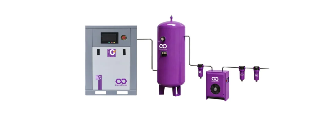
Udara terkompresi untuk keperluan pangan harus memenuhi standar ISO 8573-1 Kelas 2.2.1 atau yang lebih ketat, yang berarti adanya batas ketat terkait aerosol minyak, partikel, dan kelembapan. Selain penentuan ukuran berdasarkan CFM dan PSI, peralatan pengolahan udara terkompresi Rantai tersebut harus ditentukan agar dapat menyalurkan udara yang sesuai untuk kontak langsung maupun tidak langsung dengan makanan. Persyaratan umum:
- Penyaringan partikel hingga 0,01 mikron menggunakan filter koalesensi
- Titik embun tekanan sebesar +3°C (37°F) menggunakan pengering berpendingin untuk penggunaan umum, atau -40°C (-40°F) menggunakan pengering desikan untuk aplikasi kritis
- Penyaringan karbon aktif untuk menghilangkan uap minyak dan bau
- Pipa baja tahan karat di bagian hilir pengering untuk mencegah korosi internal
Penentuan ukuran CFM untuk aplikasi makanan harus memperhitungkan penggunaan beberapa aktuator pneumatik secara berselang-seling namun bersamaan pada jalur pengemasan, mesin pengisi, mesin penutup, dan mesin pelabel. Faktor keragaman sebesar 0,80 hingga 0,90 umumnya diterapkan pada jalur pengemasan berkecepatan tinggi.
Manufaktur Farmasi
Udara terkompresi untuk keperluan farmasi termasuk yang paling ketat dalam hal kemurnian. Standar ISO 8573-1 Kelas 1.2.1 atau Kelas 0 umumnya ditetapkan. Kompresor bebas minyak itu sendiri — yang bersertifikat sesuai ISO 8573-1 Kelas 0 untuk kandungan minyak — hanyalah titik awal. Pengolahan lanjutan harus mencapai titik embun tekanan sebesar -40°C atau lebih rendah untuk mencegah potensi pertumbuhan mikroba di dalam pipa distribusi. Penentuan ukuran juga harus memperhitungkan konsumsi udara pembersihan dari pengering desikan tanpa pemanas atau berpemanas, yang dapat mengonsumsi 10% hingga 18% dari output terukur kompresor untuk regenerasi. Jika proses membutuhkan 250 CFM udara bersih dan kering, dan pengering desikan mengonsumsi 15% untuk pembersihan, kompresor harus menghasilkan sekitar 294 CFM di saluran masuk pengering.
Manufaktur Elektronik dan Semikonduktor
Udara terkompresi untuk industri elektronik harus sangat bersih dan kering. Standar minimumnya adalah ISO 8573-1 Kelas 1.2.1, sementara banyak pabrik semikonduktor mensyaratkan Kelas 0.1.1 atau lebih tinggi. Batas partikel diukur pada 0,1 mikron, dan titik embun tekanan harus -70°C (-94°F) atau lebih rendah — yang hanya dapat dicapai dengan pengering desikan. Penentuan ukuran untuk aplikasi elektronik harus mempertimbangkan:
- Konsumsi udara pembersihan yang tinggi untuk pengering dengan titik embun -70°C (hingga 20% dari laju aliran nominal)
- Kebutuhan CFM dari beberapa mesin pick-and-place, perangkat pengujian, dan sistem inspeksi optik otomatis yang beroperasi secara bersamaan
- Penyaluran tekanan yang sangat stabil — Mesin pemasangan SMT sangat sensitif terhadap fluktuasi tekanan
Pembuatan Nitrogen
Fasilitas yang menghasilkan nitrogen di lokasi menggunakan teknologi PSA atau membran memerlukan udara terkompresi sebagai bahan baku. Kebutuhan udara dari sebuah sistem produksi nitrogen Biasanya berkisar antara 2,5 hingga 7,0 kali lipat dari output nitrogen, tergantung pada tingkat kemurnian yang dibutuhkan. Sebuah fasilitas yang memproduksi 100 CFM nitrogen dengan kemurnian 99,999% mungkin memerlukan 500 hingga 700 CFM udara terkompresi pada tekanan 8 hingga 10 bar. Kompresor harus dirancang berdasarkan faktor udara ini, bukan berdasarkan output nitrogen, sehingga produksi nitrogen menjadi salah satu aplikasi yang paling intensif dalam penggunaan kompresor di industri.
Tabel Referensi Penentuan Ukuran Aplikasi
| Industri | Target ISO 8573-1 | Rentang PSI yang Umum | Kisaran CFM yang Umum | Faktor Penentuan Ukuran Kritis |
|---|---|---|---|---|
| Makanan & Minuman | 2.2.1 hingga 1.2.1 | 100–125 | 50–2,000+ | Permintaan jalur pengemasan simultan |
| Farmasi | 1.2.1 hingga Kelas 0 | 100–150 | 50–1,000+ | Udara pembersihan pengering + titik embun -40°C |
| Elektronik | 1,2,1 hingga 0,1,1 | 90–125 | 30–500+ | Titik embun -70°C + pengendalian partikel |
| Pembuatan Nitrogen | 1,4,1 minimum | 115–145 | 100–5,000+ | Rasio faktor udara (2,5–7,0 kali keluaran N₂) |
| Pemotongan Laser | 1.3.1 hingga 1.2.1 | 145–300+ | 20–200+ | Tekanan tinggi yang stabil tanpa denyutan |
| Manufaktur Umum | 2.3.2 hingga 1.3.1 | 100–150 | 50–5,000+ | Akurasi faktor keragaman |
Kesalahan Penentuan Ukuran yang Umum Terjadi dan Menyebabkan Kerusakan Kompresor Sebelum Waktunya
Kesalahan penentuan ukuran yang paling sering terjadi dan mengakibatkan kegagalan kompresor sebelum waktunya antara lain: membeli berdasarkan daya kuda (horsepower) alih-alih CFM, mengabaikan penyesuaian daya berdasarkan ketinggian, meremehkan kerugian akibat kebocoran, menganggap semua alat beroperasi secara bersamaan, dan tidak memperhitungkan penurunan tekanan pada peralatan pengolahan — masing-masing hal tersebut dapat mengurangi kapasitas efektif sistem sebesar 15% hingga 40%.
Kesalahan 1: Membeli Kompresor Berdasarkan Daya (Horsepower)
Horsepower (HP) merupakan nilai masukan, bukan nilai keluaran. Dua kompresor 50 HP yang berbeda dari produsen yang berbeda dapat menghasilkan keluaran CFM yang sangat berbeda pada tekanan yang sama, tergantung pada efisiensi unit kompresi, efisiensi motor, kerugian pada sistem transmisi, dan optimasi desain. Kompresor bebas oli berdaya 50 HP dengan efisiensi tinggi mungkin menghasilkan 200 CFM pada tekanan 125 PSI, sedangkan model dengan efisiensi lebih rendah hanya menghasilkan 170 CFM. Perbedaan tersebut — 30 CFM — setara dengan beberapa alat pneumatik atau satu mesin pengemasan lengkap. Selalu tentukan berdasarkan CFM yang dihasilkan (FAD) pada tekanan yang dibutuhkan, bukan berdasarkan daya motor dalam satuan horsepower.
Kesalahan ke-2: Mengabaikan Pengaruh Ketinggian
Sebagaimana dijelaskan secara rinci dalam bagian CFM, ketinggian mengurangi kepadatan udara dan karenanya menurunkan output kompresor. Sebuah fasilitas yang berada pada ketinggian 4.000 kaki yang membeli kompresor dengan kapasitas terdaftar 150 CFM pada permukaan laut secara efektif hanya akan menerima sekitar 128 CFM. Jika kebutuhan alat dihitung sebesar 135 CFM, sistem tersebut akan terus-menerus mengalami kekurangan pasokan. Solusinya adalah menentukan kompresor berkapasitas lebih besar dengan kapasitas di permukaan laut yang disesuaikan dengan ketinggian, atau bekerja sama dengan produsen yang menyediakan kurva kinerja yang telah dikoreksi berdasarkan ketinggian.
Kesalahan ke-3: Meremehkan Beban Kebocoran
Kebocoran udara terkompresi adalah pencuri energi yang tak terlihat dan tak bersuara. Sebuah lubang berukuran 1/8 inci pada saluran udara terkompresi dengan tekanan 100 PSI dapat menyebabkan kebocoran sekitar 25 CFM. Selama satu tahun operasi terus-menerus, kebocoran tunggal tersebut mengakibatkan kerugian biaya listrik sekitar $3.500. Fasilitas industri dengan praktik pemeliharaan yang buruk umumnya kehilangan 20% hingga 35% udara terkompresi akibat kebocoran. Saat menentukan ukuran kompresor baru, beban kebocoran pada sistem yang ada harus diukur — idealnya melalui survei ultrasonik — dan harus diperbaiki sebelum kompresor baru dioperasikan atau secara eksplisit dimasukkan ke dalam perhitungan kebutuhan CFM.
Kesalahan ke-4: Mengabaikan Batas Tekanan Peralatan Pengolahan
Setiap pengering, filter, dan regulator yang terletak di antara kompresor dan titik penggunaan akan menguras tekanan sistem. Kompresor yang spesifikasinya disesuaikan persis dengan kebutuhan alat, tanpa memperhitungkan penurunan tekanan akibat proses pengolahan, akan menghasilkan tekanan di bawah spesifikasi pada saluran masuk alat. Batas penurunan tekanan yang tercantum pada bagian PSI dalam artikel ini harus diterapkan secara ketat.
Kesalahan ke-5: Menentukan Permintaan Puncak sebagai Permintaan Berkelanjutan
Banyak fasilitas menentukan ukuran kompresornya berdasarkan skenario teoretis di mana setiap perangkat pneumatik beroperasi secara bersamaan pada beban penuh. Dalam praktiknya, skenario ini hampir tidak pernah terjadi. Penentuan ukuran yang berlebihan berdasarkan prinsip "puncak ditambah semua beban" mengakibatkan kompresor menghabiskan sebagian besar masa operasinya pada beban parsial — di mana mesin berkecepatan tetap jauh kurang efisien. Metodologi faktor penggunaan simultan yang dijelaskan dalam bagian CFM menghasilkan spesifikasi yang lebih realistis dan lebih hemat biaya.
Kesalahan ke-6: Mengabaikan Pengaruh Suhu Lingkungan
Kinerja kompresor menurun seiring dengan meningkatnya suhu lingkungan. Udara masuk pada suhu 100°F memiliki kepadatan sekitar 6% lebih rendah dibandingkan pada suhu 68°F, sehingga mengurangi laju aliran massa. Selain itu, sistem ventilasi ruang kompresor yang tidak memadai untuk pembuangan panas mesin dapat menciptakan lingkaran umpan balik: kenaikan suhu ruangan mengurangi output kompresor, yang memicu waktu operasi yang lebih lama, yang pada gilirannya menghasilkan lebih banyak panas. Sistem ventilasi ruang kompresor yang dirancang dengan ukuran yang tepat harus menjaga suhu lingkungan tetap dalam kisaran yang ditentukan oleh pabrikan, biasanya 40°F hingga 105°F untuk kompresor sekrup rotari bebas oli.
Tanpa Oli vs. Dilumasi Oli: Pertimbangan Penentuan Ukuran untuk Masing-Masing Teknologi
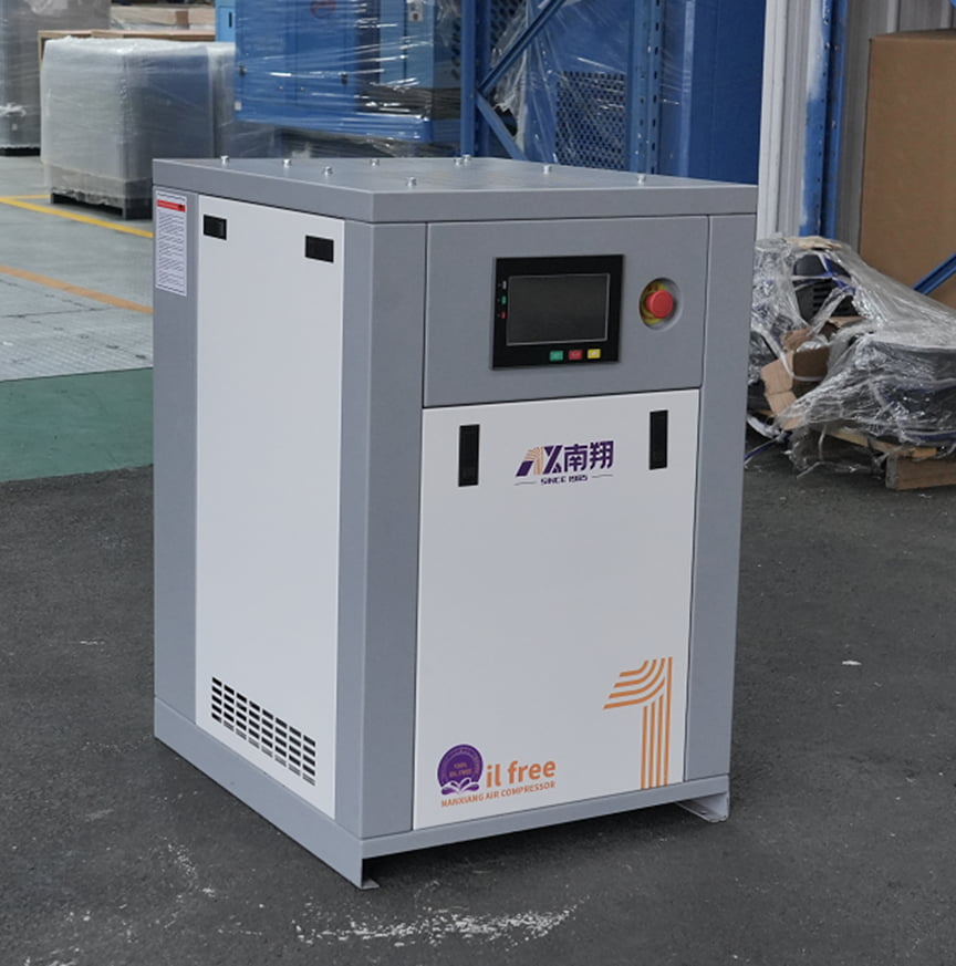
Kompresor bebas oli dan kompresor berpelumas oli memiliki batasan perhitungan ukuran yang berbeda. Mesin bebas oli biasanya beroperasi pada suhu internal yang lebih tinggi, yang menyebabkan efisiensi volumetriknya lebih rendah dibandingkan dengan kompresor berpelumas oli dengan daya yang setara. Namun, kompresor bebas oli menghilangkan risiko terbawanya oli ke dalam aliran udara terkompresi, sehingga menjadikannya satu-satunya pilihan yang layak untuk aplikasi yang memerlukan kualitas udara sesuai standar ISO 8573-1 Kelas 1 atau Kelas 0. Keputusan penentuan ukuran antara kedua teknologi tersebut melibatkan pertimbangan antara biaya modal awal, persyaratan kualitas udara, dan biaya operasional sepanjang masa pakai.
Perbandingan Efisiensi Volumetrik
Dalam sebuah kompresor sekrup putar berpelumas oli, oli yang disuntikkan memiliki tiga fungsi: pelumasan, penyegelan celah di antara rotor, dan penyerapan panas kompresi. Segel oli secara signifikan meningkatkan efisiensi volumetrik — rasio aliran udara aktual yang dihasilkan terhadap perpindahan teoretis. Kompresor sekrup bebas oli mencapai sinkronisasi rotor melalui roda gigi pengatur waktu dan mengandalkan toleransi manufaktur yang ketat, bukan lapisan oli, untuk penyegelan. Hasilnya adalah selisih efisiensi volumetrik sekitar 5% hingga 12% pada daya yang setara:
| Parameter | Berpelumas Minyak (50 HP) | Tanpa Minyak (50 HP) | Perbedaan |
|---|---|---|---|
| Debit CFM | 280 | 280 | — |
| CFM yang Dihasilkan (FAD pada 125 PSI) | 240–255 | 215–235 | 8–10% kurang |
| Suhu keluaran | 170–200°F | 350–400°F | 180–200°F lebih tinggi |
| Kebutuhan pendinginan | Sedang | Tinggi | ~30% peningkatan pembuangan panas |
| Kelas minyak sesuai ISO 8573-1 dapat dicapai | Kelas 2 minimal | Kelas 1 hingga Kelas 0 | — |
Untuk kebutuhan CFM tertentu, kompresor bebas oli biasanya memerlukan motor yang lebih besar, unit kompresi yang lebih besar, atau keduanya, dibandingkan dengan kompresor berpelumas oli yang setara. Hal ini tidak berarti bahwa teknologi bebas oli kurang efisien secara absolut — efisiensi sistem secara keseluruhan sering kali lebih menguntungkan bagi kompresor bebas oli jika beban filtrasi hilir pada sistem berpelumas oli diperhitungkan. Setiap filter koalesensi dalam rantai pengolahan udara berpelumas oli menyebabkan penurunan tekanan sebesar 1 hingga 3 PSI dan memerlukan penggantian elemen secara berkala, sehingga menambah konsumsi energi parasit dan biaya pemeliharaan.
Ketika Penggunaan Tanpa Minyak Adalah Syarat Mutlak
Beberapa aplikasi memerlukan udara terkompresi bebas minyak, baik karena peraturan maupun persyaratan proses, sehingga perbandingan spesifikasi dengan sistem berpelumas oli menjadi tidak relevan:
- Manufaktur farmasi: Peraturan FDA 21 CFR Bagian 211 dan Lampiran 1 GMP Uni Eropa mensyaratkan agar udara terkompresi yang bersentuhan dengan produk bebas dari kontaminan, termasuk minyak.
- Pengolahan makanan dan minuman: Standar SQF, BRC, dan FSSC 22000 mensyaratkan penggunaan udara terkompresi bebas minyak untuk kontak langsung maupun tidak langsung dengan makanan. ISO 8573-1 Kelas 1 merupakan standar minimum yang harus dipenuhi.
- Elektronika dan fabrikasi semikonduktor: Aerosol minyak mencemari lingkungan ruang bersih dan mengganggu proses perakitan PCB.
- Manufaktur perangkat medis: Sistem mutu ISO 13485 mensyaratkan tingkat kemurnian udara yang telah divalidasi dan memenuhi standar ISO 8573-1 Kelas 1.2.1 atau yang lebih tinggi.
- Pengecatan semprot dan pelapisan bubuk: Adanya sisa minyak dapat menyebabkan cacat permukaan — seperti efek mata ikan, lubang-lubang kecil, dan kegagalan adhesi — pada lapisan akhir.
Dalam aplikasi-aplikasi ini, pertimbangan pemilihan beralih dari “tanpa oli atau berpelumas oli” menjadi “konfigurasi kompresor tanpa oli mana yang paling sesuai dengan profil kebutuhan saya, dan rangkaian pengolahan apa yang diperlukan pada tahap hilir?”
Perbandingan Biaya Sepanjang Siklus Hidup
Harga pembelian awal yang lebih tinggi untuk teknologi bebas oli sering kali disebut-sebut sebagai hambatan. Namun, analisis total biaya kepemilikan selama masa pakai 10 tahun sering kali membalikkan kesimpulan tersebut:
| Kategori Biaya (10 tahun, kompresor 100 HP) | Berpelumas Minyak | Bebas Minyak |
|---|---|---|
| Biaya modal awal | $45.000–$65.000 | $65.000–$95.000 |
| Oli, filter, elemen pemisah | $18.000–$25.000 | $3.000–$5.000 |
| Pengolahan dan pembuangan kondensat | $8.000–$15.000 | $2.000–$4.000 |
| Energi (6.000 jam/tahun pada tarif $0,10/kWh) | $380.000–$400.000 | $375.000–$395.000 |
| Waktu henti dan risiko produksi (sisa minyak) | Bervariasi, berpotensi menimbulkan bencana besar | Hampir nol |
| Total 10 Tahun | $451.000–$505.000 | $445.000–$499.000 |
Jika biaya energi dan pemeliharaan diperhitungkan, selisih biaya total selama 10 tahun antara kompresor bebas oli dan kompresor berpelumas oli ternyata sangat kecil — dan untuk aplikasi di mana risiko terbawanya oli menimbulkan konsekuensi finansial, kompresor bebas oli merupakan pilihan yang lebih rendah risikonya dan seringkali lebih hemat biaya. Efisiensi energi kompresor bebas oli modern yang dilengkapi VSD, dikombinasikan dengan hilangnya biaya pemeliharaan dan pembuangan yang terkait dengan oli, telah secara substansial mempersempit kesenjangan biaya siklus hidup dalam dekade terakhir.
Kesimpulan
Penentuan ukuran kompresor udara bebas oli pada dasarnya merupakan proses perhitungan teknik yang terstruktur, bukan sekadar perkiraan. Ketiga parameter tersebut — CFM, PSI, dan siklus kerja — masing-masing harus ditentukan melalui analisis sistematis dan bertahap dari kebutuhan pneumatik aktual di fasilitas Anda. Lembar kerja kebutuhan CFM yang memperhitungkan penggunaan simultan, kebocoran, margin pertumbuhan, dan penyesuaian ketinggian merupakan dokumen paling berharga dalam proses pengadaan. Anggaran tekanan yang memperhitungkan setiap komponen antara saluran keluar kompresor dan saluran masuk alat mencegah kinerja yang terus-menerus di bawah standar, yang sering menjadi masalah pada sistem dengan spesifikasi yang kurang memadai. Dan spesifikasi siklus kerja 100% merupakan peringkat minimum yang dapat diterima untuk aplikasi industri apa pun di mana produksi bergantung pada ketersediaan udara terkompresi.
Keputusan penentuan ukuran yang diambil saat pemilihan peralatan memiliki konsekuensi finansial yang terus bertambah sepanjang masa pakai mesin. Kompresor yang ukurannya terlalu kecil akan mengurangi hasil produksi di setiap shift. Kompresor yang ukurannya terlalu besar akan membuang-buang energi setiap jam saat beroperasi. Titik set tekanan yang ditentukan secara tidak tepat akan meningkatkan tagihan listrik setiap bulan. Menentukan ukuran yang tepat — serta mendokumentasikan dasar perhitungan teknis untuk setiap parameter — merupakan investasi terpenting yang dapat Anda lakukan demi keandalan jangka panjang dan efisiensi biaya sistem udara terkompresi Anda.
Pertanyaan yang Sering Diajukan
Bagaimana cara mengetahui apakah kompresor udara bebas minyak yang saya gunakan saat ini ukurannya terlalu kecil?
Indikator paling andal yang menandakan kompresor berkapasitas kurang adalah alarm tekanan rendah yang terus-menerus muncul di titik penggunaan, alat-alat yang melambat atau macet saat beberapa perangkat beroperasi secara bersamaan, serta kompresor yang tidak pernah mencapai kondisi unload atau idle selama jam produksi. Jika kompresor beroperasi terus-menerus selama setiap shift tanpa pernah mati, hampir dapat dipastikan bahwa kompresor tersebut beroperasi pada atau melebihi kapasitas terukurnya. Lakukan studi pencatatan data selama satu minggu produksi yang representatif: ukur tekanan sistem pada saluran keluar kompresor, di titik penggunaan terjauh, dan di header utama. Penurunan tekanan lebih dari 10 PSI antara kompresor dan alat yang paling jauh, dikombinasikan dengan waktu pengoperasian yang terus-menerus, menegaskan bahwa sistem tersebut berukuran terlalu kecil.
Apakah saya bisa menghubungkan dua kompresor bebas oli berukuran lebih kecil sebagai pengganti membeli satu unit besar?
Ya, dan dalam banyak kasus, instalasi multi-kompresor dengan pengendali pusat menawarkan kemampuan turndown dan redundansi yang lebih baik daripada satu unit besar. Dua kompresor berdaya 75 HP yang beroperasi di bawah pengatur urutan (sequencer) dapat menyesuaikan output dengan permintaan secara lebih efisien daripada satu unit berdaya 150 HP yang beroperasi pada beban parsial. Namun, biaya instalasi total — termasuk infrastruktur kelistrikan, perpipaan, pondasi, dan sistem kontrol — umumnya lebih tinggi untuk beberapa unit. Keputusan harus mempertimbangkan nilai redundansi N+1 dan efisiensi beban parsial yang lebih baik dibandingkan dengan biaya modal dan instalasi yang lebih tinggi. Metodologi penentuan ukuran tetap sama: total CFM gabungan harus memenuhi permintaan yang dihitung dengan margin yang sesuai.
Apakah nilai CFM yang lebih tinggi selalu berarti kompresor yang lebih baik?
Tidak. CFM merupakan satuan pengukuran aliran udara, bukan indikator kualitas atau kesesuaian kompresor. Sebuah kompresor dengan nilai CFM tinggi namun stabilitas tekanan yang buruk, efisiensi rendah pada beban parsial, atau daya tahan unit udara yang tidak memadai, mungkin akan berkinerja lebih buruk saat beroperasi dibandingkan mesin yang lebih kecil, dirancang dengan lebih baik, dan disesuaikan ukurannya secara tepat untuk aplikasi tersebut. Metrik terpenting selain CFM adalah daya spesifik (kW per 100 CFM — ukuran langsung dari efisiensi energi), tingkat kebisingan, persyaratan pendinginan, serta rekam jejak pabrikan dalam hal keandalan dan dukungan purna jual. Kompresor 100 CFM dengan daya spesifik 18 kW/100 CFM akan mengonsumsi listrik yang jauh lebih sedikit selama masa pakainya dibandingkan kompresor 100 CFM dengan daya spesifik 22 kW/100 CFM, meskipun nilai CFM keduanya sama.