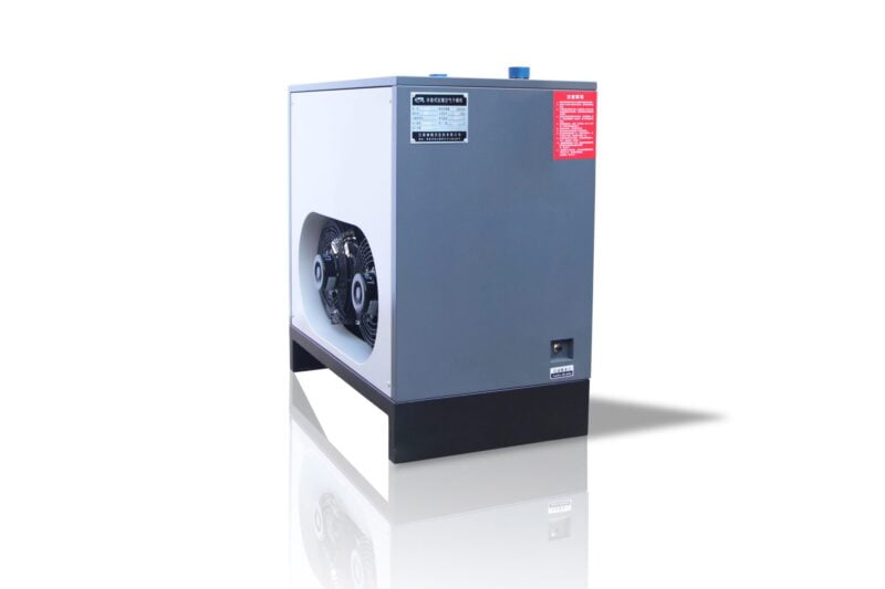
Compressed air is often treated as a utility that can be dropped into an empty corner and switched on. That assumption is expensive. A large share of premature failures, nuisance trips and unexplained pressure loss at the tool traces back to the installation rather than the machine: recirculated hot air, undersized pipe, treatment equipment connected in the wrong order, or a receiver drain nobody can reach. These faults develop slowly, so they are blamed on the equipment long after the cause has been buried under concrete.
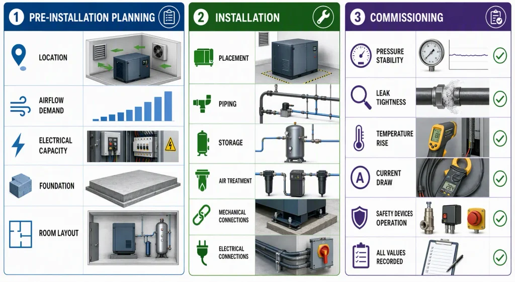
A complete industrial air compressor installation checklist runs in three phases. Pre-installation planning fixes location, airflow demand, electrical capacity, foundation and room layout before anything is delivered. Installation covers placement, piping, storage, air treatment and the mechanical and electrical connections. Commissioning proves the system against measured evidence: pressure stability, leak tightness, temperature rise, current draw and correct operation of every safety device. Each line should be signed off with a recorded value, not a verbal confirmation.
The checklist below follows that sequence and states the criteria that separate a workable installation from a permanent maintenance problem.
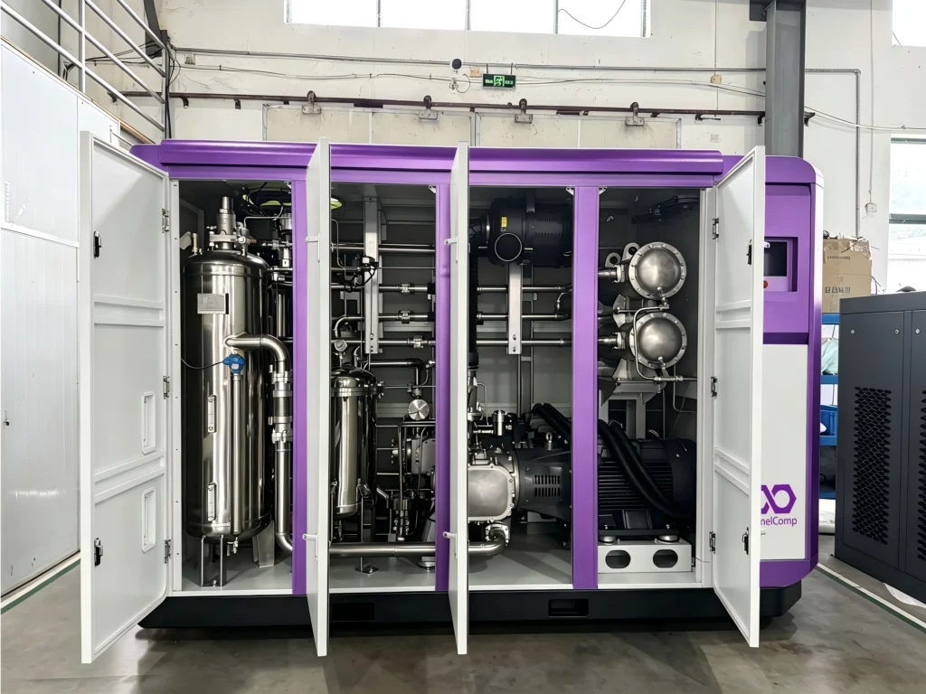
What Should an Industrial Air Compressor Installation Checklist Cover?
It should cover the four decisions hardest to reverse: site and room conditions, electrical supply capacity, the compressed air distribution network, and the commissioning evidence that proves performance. Freight inspection, training and documentation sit inside those areas rather than beside them.
Most installation failures are mismatches between what the machine needs and what the building provides. A unit rated for a 46 °C ambient installed in a room that reaches 52 °C in August loses output and oil life however well it is serviced, and a main one size too small delivers full pressure at the header and insufficient pressure at the far end of the plant.
| Phase | Core items | Sign-off evidence |
| Pre-installation | Demand survey, sizing, layout, foundation, ventilation plan, electrical capacity | Approved drawing, load calculation |
| Installation | Delivery inspection, placement, piping, receiver, treatment, wiring, grounding | Piping pressure test, electrical test sheet |
| Commissioning | No-load run, load test, leak survey, safety device check, baseline recording | Report with measured values |
Pre-Installation Planning and Site Assessment
Planning should establish the plant’s real airflow and pressure profile, confirm the room can supply clean cool air and reject heat, verify the electrical service can carry starting and running current, and prove the floor and access route can accept the unit.
Air Demand and Compressor Sizing
Sizing starts with a survey, not a nameplate. Record the flow and pressure requirement of every consumption point, then apply a simultaneity factor instead of adding peaks together. Leakage alone typically consumes 20 to 30 percent of demand, so measure it by isolating the receiver and watching pressure decay during a production pause. An Air Compressor CFM Calculator converts tool ratings, duty cycles and simultaneity into a required flow that can be compared against candidate models. Where demand swings widely, variable speed control or a mix of fixed and variable units beats one large fixed speed machine.
Room Layout, Clearances and Access
The room should be dedicated, dry, well lit and free of dust-generating or heat-generating equipment, and a central position shortens the pipe runs that create pressure loss and leakage.
| Dimension | Typical minimum | Reason |
| Side clearance to wall or equipment | 1 m (3 to 4 ft), service side wider | Filter, oil and cooler access |
| Clearance above the unit | 2 m (5 to 6 ft) | Heat discharge, lifting, rotor work |
| Spacing between parallel units | 0.8 to 1 m | Prevent one unit drawing another’s exhaust |
| Door and access route | Wider than the largest removable component | Entry and later removal |
The access route is the item most often missed. A receiver that cannot pass through the doorway forces either a room redesign or a vessel smaller than the system needs.
Foundation, Ambient Conditions and Intake Quality
Rotary screw units generally need no special foundation but do need a flat, level, load-bearing floor; correct unevenness with a grout bed or steel plate rather than shims under individual feet, which concentrate load and distort the frame. Piston compressors may need a reinforced isolated foundation. Confirm the maximum ambient the site reaches, not the average, and draw intake air from a clean, cool area: where the room is dusty or the unit sits near grinding or painting, duct the intake from a cleaner zone with a pre-filter. Outdoor installation works in moderate climates if the unit is rated for it, but the enclosure protection must be verified rather than assumed.
Electrical Supply, Protection and Safety Devices
Electrical preparation must confirm that voltage, frequency, phase and full load current match the nameplate, that the unit has a dedicated circuit with a correctly sized breaker or fused disconnect, and that frame, motor and panel are grounded to local code.
Nameplate, Circuit and Grounding Checks
Compare the nameplate with the supply before the cable is pulled. Dual voltage motors are a frequent source of destructive error, because the internal link configuration must match the supply; a unit wired for the higher voltage and connected to the lower will draw excessive current and fail within minutes. Confirm phase rotation on three phase units, since reversed rotation on a direct driven screw compressor can damage the airend before any alarm appears. Size cable and protection for starting current and voltage drop, not steady state current alone; an undersized cable produces a start dip that stresses contactors and is among the costliest items to correct later.
Relief Valves, Gauges and Receiver Safety
Every receiver needs a visible pressure gauge and spring-loaded safety valves whose combined relieving capacity prevents pressure from exceeding the maximum allowable working pressure by more than 10 percent. No valve of any type should sit between the receiver and its safety valve, and drains, handholes and manholes must stay accessible. These are regulatory requirements in many jurisdictions, and OSHA 1910.169 is a useful reference for the intent even outside the United States. Size the valve by flow as well as pressure: where two units feed a common header, downstream protection must pass the combined output of both.
Ventilation and Heat Removal
Ventilation must remove essentially all the heat the compressor and its treatment equipment reject into the room and prevent that hot air from re-entering the intake. If room temperature rises more than about 5 °C above outside ambient in operation, natural ventilation is insufficient and forced exhaust is required.
Heat Load and Airflow
Nearly all electrical input leaves as heat, so allow roughly 2,500 BTU per hour for every horsepower of connected motor load and add the dryer and other treatment equipment in the same room. Two 100 hp units therefore impose a load similar to one 200 hp machine, and the calculation must use the total. Louvered openings may suffice for small units in temperate conditions, but free area must follow required airflow at an acceptable face velocity, not machine size. Above roughly 25 hp, forced exhaust through ductwork is normally needed, with a matching makeup air path so the room does not run under negative pressure.
Duct resistance is where designs fail. Every bend adds loss, and a single 90 degree elbow can equal roughly 30 feet of straight duct, so a route with three bends, a reducer and a wall louver may need a fan sized for several times the straight-run resistance. In heating-dominated climates, add a damper so the rejected heat can be redirected to space heating in winter instead of being discharged to atmosphere.
Compressed Air Piping, Storage and Condensate Management
The distribution system should follow the sequence compressor, receiver, dryer, filters, point of use, so the receiver cools the air and drops bulk condensate before the dryer sees it. The main should be sized for low velocity and minimal pressure drop, sloped to a drain, and arranged as a loop where several departments draw air.
Pipe Sizing, Velocity and Pressure Drop
Select diameter from flow and allowable velocity, not from the discharge connection alone. Keep header velocity around 20 to 30 feet per second, design the main for no more than about 2 psi of drop, and hold total system drop under 10 percent of discharge pressure. Black iron scales internally, copper resists corrosion and is easy to modify, aluminum alloy assembles quickly and stays clean, and stainless steel suits high purity work; a rough or scaled bore behaves like a smaller pipe every year.
- Slope horizontal mains about 1 to 2 degrees toward a drain leg.
- Take branches from the top of the main, never the bottom.
- Use reducing fittings instead of abrupt diameter changes, and minimise elbows.
- Close the main into a ring so any point is fed from two directions.
- Terminate each drop with a drip leg and drain valve below the take-off.
Receiver Sizing and Placement
Storage stabilises header pressure, absorbs sudden demand and reduces load and unload cycling. A widely used benchmark is 8 to 10 gallons of storage for every CFM delivered by the largest compressor, as set out in the CAGI compressed air system design handbook. A wet receiver after the compressor handles condensate and pulsation while a dry receiver downstream of the dryer buffers the header, so larger systems benefit from both. Industrial Air Receivers should be placed so the drain, inspection openings and nameplate stay accessible, with clearance for vessel replacement.
Drains and Condensate Removal
Every low point needs drainage: receiver, dryer, filters, drip legs. Manual ball valves work only where someone is genuinely assigned to open them on schedule, so timer or zero-loss electronic traps with upstream strainers are more reliable. Route condensate through an oil-water separator before discharge, since compressor condensate carries lubricant.
Air Treatment: Dryers, Filters and Quality Targets
Treatment should be specified from required air quality, expressed as a dew point plus permissible oil and particle levels, rather than from a catalogue default. Dryer type, filter grades and their sequence follow from that specification, and the pressure loss they add belongs in the system pressure budget.
Instrument air, breathing air, food contact and general pneumatic actuation each demand a different combination of dryness and cleanliness, and the purity classes in ISO 8573-1 give buyers and suppliers a measurable language for particles, water and oil. Refrigerated dryers reach pressure dew points near 3 °C and suit general plant air where piping stays above freezing; desiccant dryers reach far lower dew points for outdoor lines and moisture-sensitive processes, at the cost of purge air and energy.
Place a coalescing filter upstream of any desiccant dryer to protect the desiccant from oil, and a particulate filter downstream to catch carryover. Fit a differential pressure gauge to every housing, because an element is a consumable whose condition must be visible. When selecting an industrial Air Compressor Dryer, confirm the rated flow is corrected for actual inlet temperature, ambient temperature and working pressure, since a unit rated at nominal conditions will be undersized in a hot plant.
Mechanical Installation and Delivery Inspection
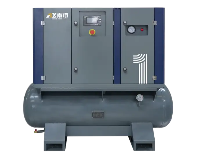
Mechanical work begins with a documented delivery inspection and ends with a level, aligned, correctly lubricated machine mechanically isolated from its piping.
Unwrap and inspect the unit before signing the receipt, looking for bent frames, cracked guards, damaged coolers and oil stains that suggest handling damage; refuse delivery on major damage and describe minor damage on the bill of lading with photographs, because a freight claim cannot be supported afterwards. Then:
- Confirm the floor is level and the base fully supported, correcting with grout rather than shims.
- Fit isolation pads and check the unit sits without rocking before anchoring.
- Install a flexible connector at the discharge and support the pipe independently.
- Remove transport plugs and fit the specified breather; many units ship with a temporary plug that must not stay in service.
- Fill lubricant to the sight glass with the specified grade and record the quantity.
- Confirm welding or grinding nearby is finished or shielded, since metal particles drawn into the airend cause irreversible damage.
Commissioning: Tests, Adjustments and Baseline Data
Commissioning verifies the installed system, not the catalogue specification. It confirms rotation, proves pressure build-up and stability under load, verifies leak tightness, tests every safety device, and records a baseline that later maintenance can be judged against.
- Confirm isolation is removed, guards fitted and the discharge path to the receiver open.
- Bump start to confirm rotation direction, then stop immediately.
- Run unloaded for 15 to 30 minutes with the receiver drain open, listening for abnormal noise.
- Close the drain and let the unit build to set point, watching for leaks and abnormal temperature rise.
- Load gradually and observe pressure stability at the header and at the furthest point of use.
- Verify inlet valve and loading settings, and confirm sump pressure holds during unload.
- Test the relief valve and confirm the gauge reads correctly.
- Record every value and hand the record to the plant.
Leak Testing and Baseline Recording
Survey the whole installation, not only the compressor connections. Soap solution suits accessible joints while ultrasonic detection is faster on a large network, and watch the condensate path after the moisture separator, where moisture points to a trap fault rather than a leak.
Record discharge pressure and temperature, header pressure, flow at a known load, current per phase, room ambient, pressure drop across each filter, dryer dew point and the loading pattern over a representative shift. Those values are the only reliable way to separate normal ageing from a developing fault. A single unit with a short piping run normally needs one working day on site.
Documentation, Operator Training and Handover
Handover is complete only when the plant holds drawings, test records, settings, spares list and warranty terms, and when the people who run the machine are trained on startup, shutdown, alarm response and isolation.
The package should include as-built drawings, electrical schematics, the commissioning report, controller settings, the maintenance schedule with the first oil and filter interval, and warranty conditions covering documented servicing. Training must cover the meaning of each alarm and trip, response to high discharge temperature and low oil pressure, safe isolation before intervention, and what not to touch: relief valves, set points, interlocks. A maintenance plan agreed at handover, backed by responsive Service Support, prevents the common pattern of a sound installation degrading within a year.
Common Installation Mistakes and How to Avoid Them
Most problems fall into a few recurring categories: an undersized or overheated room, inadequate electrical supply, a network designed for appearance rather than pressure drop, missing storage, and a commissioning stage skipped because the plant wants to start production.
| Mistake | Consequence | Correction |
| Room too small or low ceiling | Recirculation, temperature trips, short oil life | Recalculate heat load, add exhaust and makeup air |
| Inlet and exhaust on the same wall | Exhaust re-enters the intake | Separate them, or duct the discharge away |
| Main sized from the discharge connection | High velocity, pressure loss at the far end | Resize from flow and allowable velocity |
| Branches from the bottom of the main | Condensate carried into tools | Take branches from the top, add drip legs |
| No receiver or minimal storage | Rapid cycling, pressure swings | Add storage at 8 to 10 gallons per CFM |
| Undersized cable or shared circuit | Start voltage dip, motor stress | Dedicated circuit sized for starting current |
| Delivery accepted without inspection | Unresolved freight damage, disputed claims | Inspect before signing, photograph everything |

FAQ
Do I need a permit or pressure vessel inspection for a new air receiver?
In many jurisdictions a receiver above a defined volume and pressure threshold is a regulated vessel that must be registered and sometimes inspected before or shortly after entering service. Thresholds and inspection intervals vary by region, so confirm the local requirement before ordering. Keep the manufacturer’s declaration, material certificates and relief valve data, because they are normally requested during registration.
Can an air compressor share a room with a boiler or furnace?
It is possible but rarely advisable, since combustion equipment raises ambient temperature and can carry combustion products into the intake. If shared space is unavoidable, duct the intake from outside, verify the ventilation can remove the combined heat load, and confirm the compressor’s ambient rating is not exceeded at the worst summer condition.
Does the checklist change for an oil-free compressor?
The structure stays the same but several items tighten. Oil-free machines are more sensitive to intake quality, so filtration and intake location matter more. Cooling is often water based, which adds water quality, flow and temperature checks to commissioning. With no oil to carry heat from the compression chamber, discharge temperature limits are tighter, and cooler performance must be verified against design values.
Installing an industrial compressor is a sequence of decisions that become progressively harder to change. Site conditions, electrical capacity and room layout are settled on paper, piping and storage during construction, performance at commissioning. The checklist earns its keep only when each line ends with a measured value and a signature.