Compressed air is the utility most plants treat as free until a batch is rejected. An oil aerosol invisible on a pressure gauge can spoil a food line, contaminate a sterile filling zone or ruin a wafer, and that risk has pushed a growing share of buyers toward oil-free compressors.
An oil-free rotary screw air compressor compresses air between two intermeshing helical rotors that never touch each other or the casing, so no oil is needed in the compression chamber to lubricate surfaces or seal the gaps. Precisely machined clearances, a pair of timing gears and dry-running rotor coatings keep the rotors synchronized and limit leakage. Because a dry element tolerates a pressure ratio of only about 3.5, the air is compressed in two stages with an intercooler between them, then aftercooled and discharged as oil-free air.
The sections below follow the air from inlet filter to discharge flange, then examine what that architecture costs.
Are Rotary Screw Air Compressors Oil-Free?
No, not by default. Rotary screw is a machine architecture, not a purity rating. The same twin-rotor geometry is built in oil-injected and oil-free versions, and the difference is whether a lubricant is injected into the compression chamber. Oil-free describes where the oil is kept, not whether the machine contains oil at all.
In an oil-injected compressor, oil sprayed into the rotor mesh seals the clearance gaps, carries away the heat of compression and lubricates the bearings, which is why one stage reaches 7 to 13 bar at roughly 80 °C.
Where the Oil Still Works
Oil still lubricates the timing gears, shaft bearings and drive gearbox, sealed off from the air path by labyrinth and carbon ring seals plus, on many designs, a barrier air feed holding slight positive pressure toward the sump. Seepage therefore travels outward, not into the chamber. What disappears is the separator element, the carryover and the oily condensate.
Three Ways to Build an Oil-Free Screw
| Design | What seals the gaps | Stages to 7 to 8 bar | Stage 1 discharge |
| Dry screw, non-contacting | Tight clearances and coating | Two | 160 to 180 °C |
| Water-lubricated screw | Injected water | One or two | 70 to 90 °C |
| Oil-injected plus filters | Oil, then filtration | One | About 80 °C |
Injecting water instead of oil restores sealing and cooling and allows a higher pressure ratio per stage, but it adds a treatment loop and a bacterial growth risk.
The Compression Path, Stage by Stage
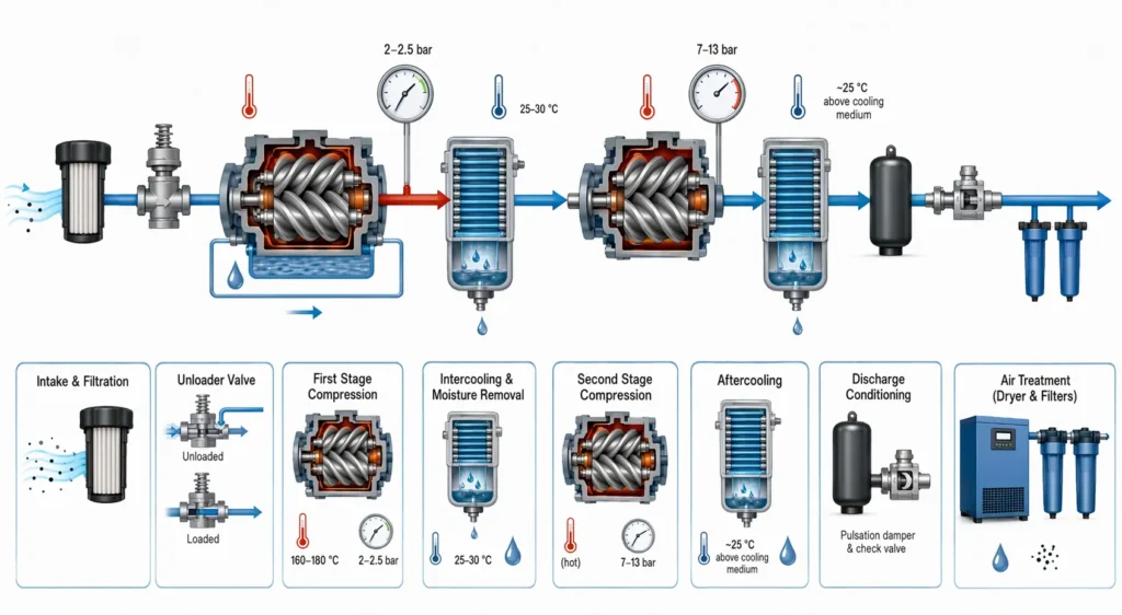
Filtered ambient air enters the first-stage rotor pair, is compressed to about 2 to 2.5 bar and heated to 160 to 180 °C, passes through an intercooler that drops it to 25 to 30 °C and removes condensed water, then enters the second-stage rotor pair, which raises it to the final 7 to 13 bar before an aftercooler cools it again.
Intake and First Stage
Air passes an inlet filter rated for particles in the low single-digit micron range and an unloader valve that switches the machine between loaded and unloaded. With no oil film to absorb heat, the first stage runs far hotter than a lubricated equivalent, so its casing is cooled by water jackets or an external oil or air stream.
Intercooling and Moisture Removal
Cooling between stages reduces the work the second stage must perform, protects the high-pressure element and condenses much of the inlet water vapor, which a separator downstream collects.
Second Stage, Aftercooling and Discharge
The high-pressure element takes the cooled air to final pressure, then a pulsation damper smooths the discharge pulse and a check valve prevents backflow on shutdown. The aftercooler brings the air to roughly 25 °C above the cooling medium, and from there it goes to a dryer and filters, because oil-free compression says nothing about water or particles.
| Point in the path | Pressure | Temperature | What happens |
| Stage 1 discharge | 2 to 2.5 bar | 160 to 180 °C | First compression |
| Intercooler outlet | Slightly lower | 25 to 30 °C | Heat removal, condensate drop-out |
| Stage 2 discharge | 7 to 13 bar | 140 to 175 °C | Final compression |
Why Two Stages Instead of One?
Because a dry screw element has no oil film to seal the gaps or carry heat away, its pressure ratio is limited to about 3.5 per stage. Compressing straight to 7 bar in one dry stage would push rotor and casing temperatures past what the clearances and coatings can survive, so two elements are placed in series with an intercooler between them.
Pressure ratio is outlet absolute pressure divided by inlet absolute pressure. An oil-injected element handles a ratio near 13 in one step; a dry element handles about 3.5. Splitting the duty also saves energy, because returning the air to near ambient between stages brings the process closer to isothermal compression.
The penalty is mechanical: two elements, a gearbox driving both from one motor, tighter tolerances and a larger package. The stages are also matched, since everything the first stage delivers must be swallowed by the second, and a worn coating shows up as drifting interstage pressure long before it becomes a failure.
Inside the Airend: Rotors, Timing Gears and Clearances
A male rotor with convex lobes drives a female rotor with matching flutes, turning in opposite directions inside a closely fitted casing. A pair of timing gears at the shaft end keeps them synchronized so the lobes pass with a clearance measured in hundredths of a millimeter, and that clearance, together with the rotor coating, is what controls internal leakage.
As the rotors turn, the space between lobes and casing closes, so a fixed volume of air is trapped, moved axially and squeezed toward the discharge port. That geometry decides the rotary screw air end efficiency more than any other factor.
Rotor Profile and Surface Treatment
Because the rotors never touch, surfaces carry PTFE, molybdenum-based or diamond-like carbon coatings to reduce friction during transient contact and protect base metal from corrosion.
Timing Gears, Bearings and Shaft Seals
The gears exist because the rotors must not drive one another. In an oil-injected element the oil film lets the male rotor push the female, but a dry element would destroy itself in seconds under that contact. All bearings sit on the oil side of the shaft seals.
Cooling Circuits and Heat Recovery
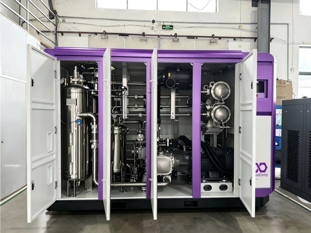
An oil-free rotary screw compressor runs two separate cooling circuits. Water or air removes heat from the compressed air at the intercooler and aftercooler and from the element casings, while a small oil circuit cools and lubricates the gears and bearings. The two never mix, and that separation is exactly what keeps the air oil-free.
On water-cooled units the circuit is often split, with one loop serving the low-pressure element and intercooler and another serving the high-pressure element and aftercooler.
Because nearly all shaft power ends up as heat, 70 to 90 percent of that input can often be recovered as hot water at 60 to 90 °C for washdown or boiler feedwater.
What “Oil-Free” Actually Guarantees Under ISO 8573-1
It guarantees that no lubricant is introduced into the compression chamber, and a certified dry machine can be verified to Class 0 for oil under ISO 8573-1, the international standard for compressed air purity. It does not guarantee that the air reaching your process is clean, because water, particles and gaseous contaminants are separate classes in the same standard.
| Oil class | Total oil content | Typical source |
| Class 0 | Set by user and supplier, below Class 1 | Certified oil-free compression |
| Class 1 | 0.01 mg/m³ or less | Oil-free, or oil-injected with full filtration |
| Class 2 | 0.1 mg/m³ or less | Oil-injected with coalescing filters |
| Class 3 | 1 mg/m³ or less | Oil-injected, basic filtration |
| Class 4 | 5 mg/m³ or less | Unfiltered lubricated compressor |
The distinction that matters commercially is between oil-free and technically oil-free, the latter being an oil-injected compressor followed by coalescing and carbon filters, which can reach Class 1 on a good day. Filter performance degrades with age, and a separator failure sends a slug of oil downstream within minutes.
Where Oil-Free Rotary Screw Compressors Are Used
They are used wherever compressed air touches the product, the packaging, a medical device or a human breath, where a single oil aerosol is a batch rejection rather than a maintenance nuisance.
| Industry | Typical duty | What drives the choice |
| Food and beverage | Direct-contact aeration, PET blow moulding | Hygiene standards and recall risk |
| Pharmaceutical | Fermentation air, coating, cleanrooms | GMP compliance and validated purity |
| Electronics | Cleanroom air, wafer handling, assembly | Particle and oil limits at point of use |
| Medical and dental | Breathing air, sterilizers, instrument air | Regulatory limits on oil content |
The Downsides of Oil-Free Rotary Screw Air Compressors
The main downsides are a higher purchase price, slightly higher energy consumption per cubic meter of air, greater sensitivity to inlet dust and cooling quality, and more expensive repairs when an element or gearbox fails.
At equal motor power, purchase price typically runs 30 to 60 percent above an oil-injected machine, and specific power is commonly 3 to 8 percent higher at the same pressure. Airend overhauls need specialist service, and part-load performance is only competitive with variable speed control.
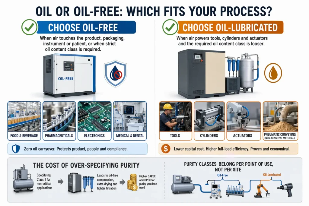
Oil-Free or Oil-Lubricated: Which Is Better?
Neither is better in the abstract. If the air never touches the product or a person, an oil-lubricated air compressor will usually deliver the same flow for less capital and less energy. If the air does touch the product, the filtration, monitoring and contamination risk of the lubricated route normally cost more than the oil-free premium.
| Decision factor | Favors oil-free | Favors oil-injected |
| Air contacts product or patient | Yes | No |
| Audit or certification exposure | High | Low |
| Annual running hours | Low to moderate | Very high, energy dominated |
Electricity is usually the largest item in a compressor’s lifecycle cost, so a three to eight percent efficiency gap becomes significant at high hours. That argues for comparing total cost over ten years rather than sticker price. Within the oil-free family, a single-stage vs two-stage comparison matters just as much, since a two-stage machine only earns its extra cost on continuous duty.
Maintenance and Specification Notes
Maintenance shifts from oil changes to air-path cleanliness. Inlet filter condition, cooler cleanliness, shaft seal integrity, gearbox oil condition and the interstage pressure trend are the five items that decide whether an oil-free element reaches its design life.
- Replace inlet elements on differential pressure, not calendar interval alone.
- Clean intercooler and aftercooler on a schedule, more often in dusty sites.
- Check barrier air and seal leakage whenever gearbox oil consumption rises.
When specifying, confirm delivered flow at your actual pressure rather than a nominal rating, and ask for data measured to the acceptance test standards published by the compressed air industry association.
FAQ
Can you run an oil-free air compressor on its side?
Not if it is a rotary screw machine. The airend, gearbox and oil sump need level mounting, and tilting the unit starves bearings and can flood the air side with oil. Small portable oilless units are sometimes built to run in any orientation, but that is a design feature to confirm for the exact model.
How long does an oil-free screw element last?
With clean inlet air, correct cooling and steady temperatures, a dry element commonly runs 40,000 to 60,000 hours before coatings and clearances reach the point where flow and efficiency fall noticeably. Frequent hot starts and repeated high-temperature trips can halve that.
Can an oil-free rotary screw compressor run in high ambient temperatures?
It can, but the package must be selected for it. Output derates as inlet temperature rises and motor thermal margin shrinks, so a unit sized on a 25 °C datasheet will be short of air in a 45 °C plant room.