Food, pharmaceutical, electronics and medical plants share a constraint most factories never face: the air touches the product, the packaging, the instrument or the patient, so a trace of oil is a batch loss rather than a maintenance line item. A scroll package sized for a pilot line handles that duty quietly. Three years later the same plant runs two shifts, has added a filling head and a second cleanroom, and the machine that was right at commissioning now cycles hard and holds pressure badly.
Oil-free scroll wins below roughly 100 to 150 CFM when demand is intermittent, the machine sits close to people and floor space is tight. Oil-free screw takes over once peak flow passes that band, discharge pressure climbs toward 13 bar, or the plant moves to continuous multi-shift operation. The trigger is rarely peak CFM alone, it is the average-to-peak ratio, the annual running hours and the cost of stacking one more scroll module onto a frame that was never designed for it.
The sections below follow the order in which those factors usually decide a project.
Where the Two Technologies Actually Differ
Both are dry-running positive displacement machines that keep oil out of the compression chamber, so the choice is not about purity at source. It is about how each design seals, how it modulates capacity and whether it can be brought back to specification in place.
Both designs sit in the same oil-free compressors family and carry the same purity claim, which is why the difference is so often misread as a marketing argument. The engineering difference is the sealing path and the service model.
How an Oil-Free Scroll Compresses Air
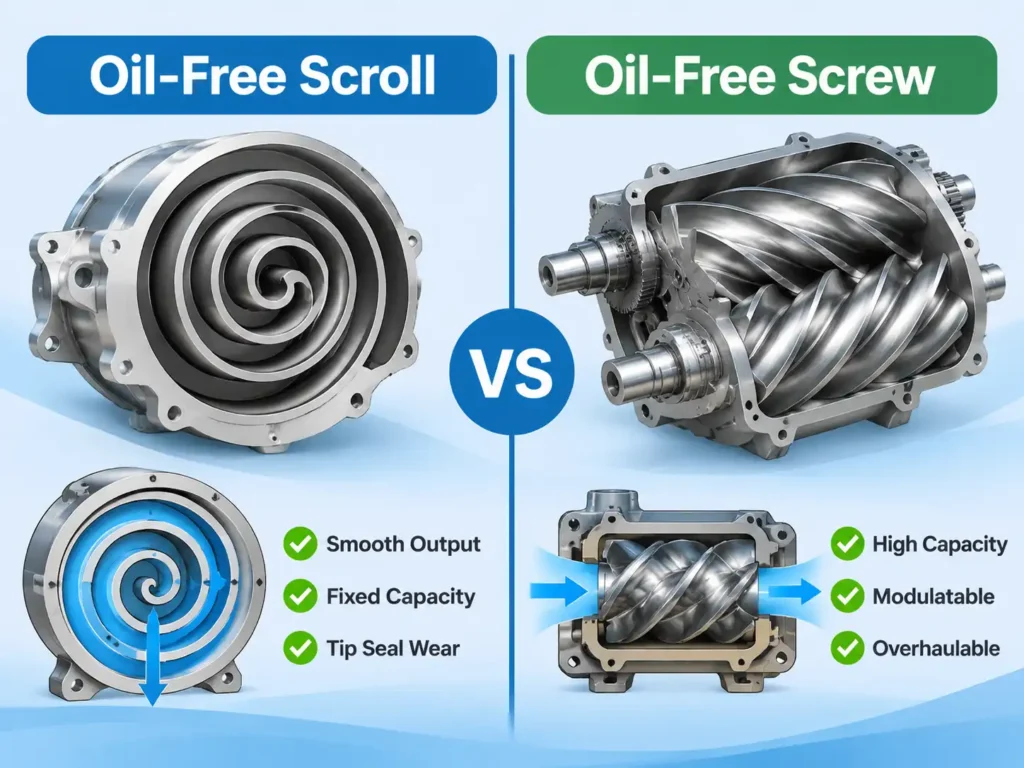
Two interleaved spiral wraps form the element. One wrap is fixed, the other orbits in a small circle without rotating, and the crescent pockets between them migrate inward and shrink, pushing air toward a central discharge port. There are no inlet or discharge valves and no contact between the wraps in normal operation. Sealing is held by polymer tip seals that bridge the gap between wrap faces and the opposite plate, and that single detail explains most of the scroll’s behaviour over its life:
- Delivery is smooth and nearly pulsation-free, which suits instruments and analysers.
- Displacement is fixed, so capacity changes only by stopping and starting the unit or switching whole modules.
- Internal leakage grows as the tip seals wear, so efficiency drifts gradually rather than failing suddenly.
- The element is not built for field rebuild, so end of life means a cartridge or a new unit.
How an Oil-Free Screw Compresses Air
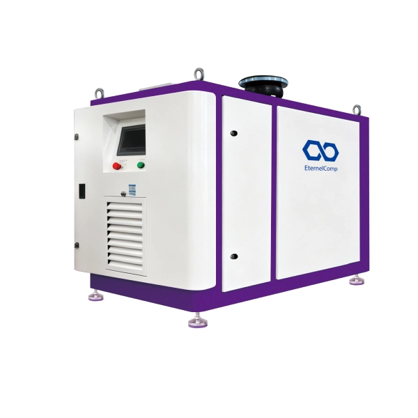
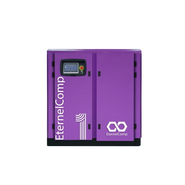
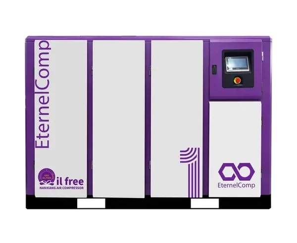
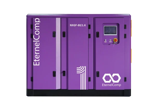
Two meshing helical rotors compress air as the thread volume closes. The rotors never touch; timing gears hold the phase and clearances measured in thousandths of an inch maintain the seal. Bearings and gears sit in a lubricated housing, isolated from the air path by shaft seals and, on many designs, by a buffer arrangement that keeps any migration direction outward. That architecture behaves differently:
- Capacity scales with rotor size, so one air end covers a range that would need many scroll modules.
- Clearances are set by machining, so efficiency stays stable until a seal or bearing event occurs.
- Capacity can be modulated continuously with a slide valve, inlet throttling or a variable speed drive.
- The air end can be overhauled with new bearings and seals, given the right service organisation.
What the Difference Means for a Growing Plant
| Parameter | Oil-free scroll | Oil-free screw |
| Compression principle | Two interleaved wraps, one orbiting | Two meshing rotors, no contact |
| Capacity control | Fixed displacement, on/off or module staging | Slide valve, inlet modulation or VSD |
| Purity risk path | Tip seal and bearing seal wear | Shaft seal and seal air system |
| Service model | Cartridge or unit replacement | In-place air end overhaul |
| Typical unit capacity | 2 to 150 CFM | 30 to 400 CFM |
Capacity and Pressure: Where Scroll Runs Out of Room
A single scroll element tops out near 15 CFM and a multi-module package near 125 to 150 CFM, while one dry screw unit starts around 30 CFM and reaches several hundred. That gap, not preference, removes scroll from consideration in most expansion projects before efficiency is even discussed.
Single Scroll, Multi-Scroll and the Module Stacking Limit
The smallest packages deliver 2 to 15 CFM and cover a dental surgery, a laboratory bench or a single instrument point. Above that, manufacturers stack identical elements inside one enclosure, each with its own intake, cooling and seal set, and a controller that starts modules in sequence as pressure falls. That gives 60 to 125 CFM in a footprint that still fits a plant room, with redundancy almost for free, because one failed module leaves the rest running.
The economics reverse at the top of that range. Once a package carries more than four to six modules, floor area per CFM, interconnecting pipework, controller complexity and the number of seal sets to service all grow faster than capacity. A single screw air end then delivers the same flow from one machine with one consumable list, which is the practical definition of the scale-up point.
The Pressure Ceiling and Which Processes Hit It
Single-stage scroll packages are normally rated at 7 to 10 bar. Two-stage scroll designs reach higher, but the added stage erodes the simplicity that justified scroll in the first place. A two-stage oil-free screw machine reaches 13 bar as a routine configuration, and beyond that a booster becomes the sensible answer for either technology. Pressure also changes quoted flow: a unit rated at 8.5 CFM on 7 bar delivers noticeably less at 10 bar, which is why catalogue figures taken at different pressure points cause so many sizing errors.
| Capacity band | Oil-free scroll | Oil-free screw |
| Flow per unit | 2 to 150 CFM | 30 to 400 CFM |
| Discharge pressure | 7 to 10 bar, higher in two stages | 7 to 13 bar |
| Typical motor size | 2 to 30 kW | 22 to 250 kW |
| Continuous duty | Model and cooling dependent | Standard |
Duty Cycle and Part-Load Efficiency: The Trigger Most Projects Miss
A scroll package can hold oil-free air at 100 percent duty, but its fixed displacement makes it a poor match for a plant that swings between 30 and 100 percent of capacity all day. Above roughly 4,000 running hours a year, the part-load behaviour of a screw package usually outweighs the scroll’s lower entry price.
Fixed Displacement, Stepped Control and Pressure Sawtooth
A fixed-speed scroll produces a fixed volume per revolution. Capacity is matched to demand by stopping the unit at the upper set point and restarting it at the lower one, or on a multi-module package by switching whole elements in and out. Flow therefore arrives in steps and the pressure trace between them is a sawtooth rather than a flat line.
Three consequences follow. Receiver volume has to absorb the steps, so too little storage cycles the machine far more often than the motor and contactor are designed for. Every start carries inrush current and a thermal penalty continuous running does not. And a plant whose average demand sits between two module sizes will either run one module loaded and dump the surplus or run two lightly, both of which waste energy in a way a full-load figure never shows. A screw package with a slide valve or drive follows demand along a curve instead of a staircase, and the advantage is largest exactly where growth projects land: a plant that doubled its average flow but still peaks for two hours a day.
Comparing Specific Power on the Same Basis
Specific power, kW per CFM, is only meaningful when both machines are rated at the same discharge pressure, the same inlet conditions and inside the same boundary. Counting the dryer and filters on one side but not the other is enough to reverse a conclusion. The industry publishes third-party verified performance data for exactly this reason, and the Compressed Air and Gas Institute runs the verification programme that makes those sheets comparable across suppliers. Two rules keep the comparison honest: ask for flow at the pressure the plant actually runs, and convert both options to annual kWh at the measured load profile rather than at rated capacity.
Air Purity After Scale-Up: Same Class, Different Proof
Both technologies deliver oil-free air at the source, so scaling up does not change the class a plant can reach. What changes is the treatment train around the compressor and the evidence available on the day of an audit.
ISO 8573-1 sets purity classes along three axes, particles, water and oil, and a specification is written as a string of numbers rather than a single grade. Class 0 is not a fixed table entry; it is a class agreed between user and supplier that is tighter than class 1, which is why two machines both described as class 0 can carry very different test evidence.
The credible oil entry path differs by design. On a scroll unit it is the bearing seal and, indirectly, tip seal condition, because a worn tip seal raises internal leakage and discharge temperature and shortens the life of everything downstream. On a screw unit it is the shaft seal and buffer arrangement, which is why seal monitoring and seal air pressure alarms matter more than the headline purity claim. Where the process is a sterile fill line or a semiconductor tool, the treatment train carries equal weight: a refrigerated dryer for instrument air, a desiccant dryer where the pressure dew point must stay well below freezing, and filtration matched to the particle class.
| Purity consideration | Oil-free scroll | Oil-free screw |
| Credible oil entry path | Bearing seal, tip seal wear | Shaft seal, seal air system |
| Purity trend over life | Gradual drift as seals wear | Stable until a seal event |
| Treatment train at equal flow | Smaller dryer, fewer drains | Larger dryer, more instruments |
| Audit documentation | Per-unit test report | Validation documents, trend data |
Noise, Footprint and Installation: The Constraints That Tighten as You Scale
Scroll keeps a real noise advantage at small sizes, but not an unlimited one: at 100 CFM a multi-module enclosure is much closer to a screw package than to the 48 dBA quoted for a 5 hp unit. Floor area per CFM is usually the constraint that tightens first.
Noise figures need a common basis before they are compared. A value quoted at one metre is a sound pressure level that depends on the room; sound power describes the machine itself and is always numerically higher. Placing one supplier’s sound pressure figure beside another’s sound power figure creates a difference that does not exist in the room. Heat rejection follows power rather than technology, since almost all shaft power ends up as heat in the plant room, so doubling flow doubles the ventilation duty whoever built the compressor.
| Criterion | Oil-free scroll | Oil-free screw |
| Noise at typical rating | 48 to 70 dBA | 70 to 80 dBA |
| Floor area per 100 CFM | High, grows with module count | Low |
| Heat rejection | Distributed, easier to ventilate | Concentrated, needs ducting |
| Point-of-use installation | Practical | Rarely practical |
Maintenance, Service Life and Redundancy
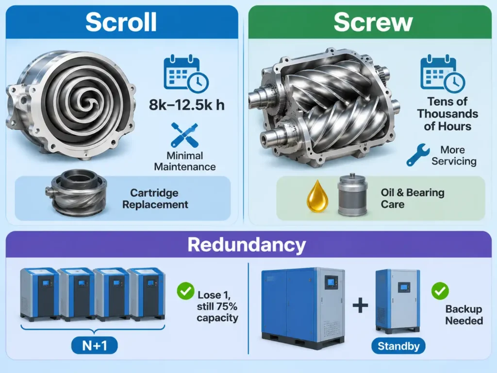
Scroll asks for less routine work but is harder to rebuild; screw asks for more consumables but can be returned to specification in place. The redundancy model flips as well: scrolls provide N+1 by module, while a single screw machine needs a partner unit or a stored reserve.
Scroll Service Profile
With no valves or connecting rods in the compression path, routine work is limited to intake filters, cooling surfaces, seal inspection and bearing checks at long intervals, and there is no air-path oil to analyse. Typical guidance puts tip seal inspection in the 8,000 to 12,500 hour band. A documented oil free air compressor maintenance schedule of this kind is undemanding, but the counterweight is repairability: when wrap faces or bearings reach their limit, the answer is a cartridge or a new unit at a large fraction of new-machine cost.
Screw Service Profile
A dry screw package carries a longer list: intake filter, shaft seals, seal air filters, bearing grease or gearbox oil, cooler cleaning and vibration checks. The oil that remains lubricates bearings and gears and never touches the air, but analysing it is still the cheapest early warning of bearing distress. The air end is expected to run tens of thousands of hours and can then be overhauled, which keeps the second decade of ownership cheaper than repeated cartridge replacement.
Redundancy: N+1 Across Modules Versus One Base-Load Machine
A four-module scroll package is inherently redundant; losing one module costs a quarter of capacity. A single screw machine is a single point of failure, so critical plants specify duplex operation, a standby unit or enough receiver storage to ride through a repair. That standby capacity belongs in the comparison, because a plant that adds redundancy only after choosing one large machine has paid for it twice.
| Task | Oil-free scroll | Oil-free screw |
| Intake filter | 2,000 hours or condition based | 2,000 hours or condition based |
| Seal inspection | Tip seals at 8,000 to 12,500 hours | Shaft seals by leak trend |
| Fluid analysis | Not applicable | Gearbox or bearing oil |
| Major intervention | Cartridge or unit replacement | Air end overhaul |
Total Cost of Ownership: Where the Crossover Point Sits
Purchase price decides very little at this scale. Energy is commonly 70 to 80 percent of a compressor’s ten-year cost, so the crossover between stacked scrolls and a screw package is set by running hours and load profile, not by the quotation.
A defensible comparison follows four steps:
- Log demand for at least two weeks, weekends and night shift included, and record average and peak flow at the pressure the plant actually needs.
- Convert each option to annual kWh at that measured profile rather than at rated capacity, including part-load hours and unloading losses.
- Add consumables at the specified intervals and price the seal or air end intervention that falls inside the evaluation period.
- Add the installation items that differ: electrical service and starting method, receiver volume, dryer capacity and ventilation.
An oil-free air compressor TCO model built this way is where most projects discover that the cheaper machine at purchase is not the cheaper machine at year eight, particularly when the load profile includes long hours below half capacity.
| Operating scenario | Load profile | Technology tendency |
| 1,500 hours a year | Intermittent, single shift | Single or duplex scroll |
| 4,000 hours a year | Two shifts, moderate swing | Multi-module scroll or small screw |
| 7,000 hours a year | Continuous, high average load | Oil-free screw with VSD |
A Practical Scale-Up Decision Framework
Start with peak flow, then test the answer against duty cycle, pressure and noise. In most plants the first test settles it, and the second one changes the answer in maybe one project in five.
| Peak flow | Typical fit | Reason |
| Under 25 CFM | Single scroll, point of use | Noise, footprint and simplicity favour scroll |
| 25 to 60 CFM | Multi-module scroll | Capacity with built-in N+1 |
| 60 to 125 CFM | Multi-module scroll, plan an exit | Workable, but module count is rising |
| 125 to 250 CFM | Oil-free screw | Module stacking stops being rational |
| 250 to 400 CFM | Two-stage or VSD screw | Pressure and part-load efficiency |
| Above 400 CFM | Centrifugal machines | Flow where positive displacement loses its edge |
Beyond the top of that band, centrifugal air compressors take over where flow is continuous and pressure moderate. Two decisions at first installation save most of the pain later: reserve floor area and ventilation for a larger frame, and size the electrical service for the machine the plant expects to need rather than the one it needs today.
The Hybrid Option: Screw Base Load with Scroll Trim
Where demand grew in steps rather than smoothly, the efficient answer is often both technologies in one system. A screw machine runs as base load inside a narrow pressure band and the existing scroll package trims the peaks instead of being retired. The arrangement needs a shared receiver, a sequencing controller that gives the screw priority and a band wide enough to stop the scroll short cycling. It preserves capital already spent and avoids buying screw capacity for two hours a day.
FAQ
Three questions tend to surface once the flow band points to screw but the budget cycle points to one more scroll module.
Can scroll modules be added one at a time as demand grows?
Usually yes, within the limits of the frame and the controller. Check spare module positions, controller input and output capacity, and receiver volume sized for the number of starts the larger package will make. Adding a module later almost always costs more per CFM than ordering the larger frame once, because the enclosure, cooling and controls are already paid for.
What electrical and receiver changes come with the step up to screw?
The supply is the first item. A 30 kW screw machine may need a different starting method from the scroll package it replaces, and direct-on-line starting can disturb other loads on a weak supply, which pushes the project toward star-delta or a variable speed drive. Cable size, breaker coordination and protection follow. On the air side, load and unload control needs more storage than module staging did, so the receiver is normally resized at the same time.
Is an oil-free screw compressor workable in a small plant room?
It can be, but the room has to be evaluated as a system rather than as floor area. A screw package rejects its heat in one place, so ventilation or ducting must be designed for the full motor input, and 70 to 80 dBA usually requires a wall between machine and occupied space or acoustic treatment. Where the room cannot be modified, a distributed layout of scroll packages in two locations often solves the same problem for less money.